Electrical receptacle connector

A technology of electrical connectors and sockets, which is applied in the direction of connection and connection device parts, circuits, etc., can solve the problems that the tongue of the electrical connector is easy to wear and deform, repair or replace it together, and break, so as to improve the overall Structural strength, reduced maintenance costs, avoiding wear and deformation effects

Active Publication Date: 2020-03-24
VITECK
View PDF4 Cites 0 Cited by
  • Summary
  • Abstract
  • Description
  • Claims
  • Application Information

AI Technical Summary

Problems solved by technology

However, with the increase in the number of plugging and unplugging of the electrical connector, the tongue of the electrical connector is easily worn, deformed or even broken
Since the electrical socket connector is usually built directly on the main board of the electronic device, when the tongue of the electrical socket connector is worn or broken, the main board of the electronic device needs to be repaired or replaced at the same time, resulting in maintenance costs high
In addition, in response to the demand for massive data transmission, electrical connectors are gradually developing towards high frequency and high speed to shorten data transmission time. However, signals are prone to interfere with each other during high frequency and high speed transmission, which affects the transmission performance of electrical connectors.

Method used


Image

  • Electrical receptacle connector
  • Electrical receptacle connector
  • Electrical receptacle connector

Examples


Embodiment Construction

[0094] The directional terms mentioned in the following embodiments, such as: up, down, left, right, front or back, etc., are only directions referring to the attached drawings. Accordingly, the directional terms are used to illustrate and not to limit the invention.

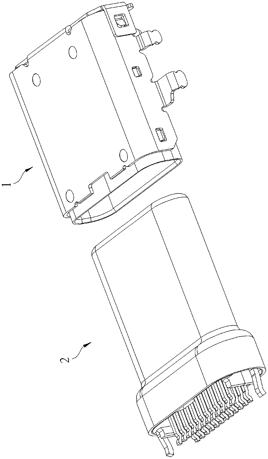
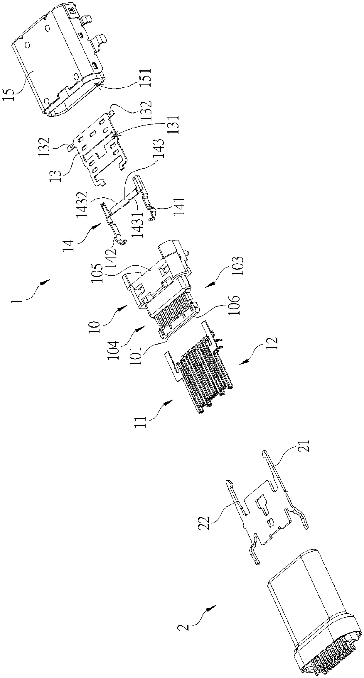
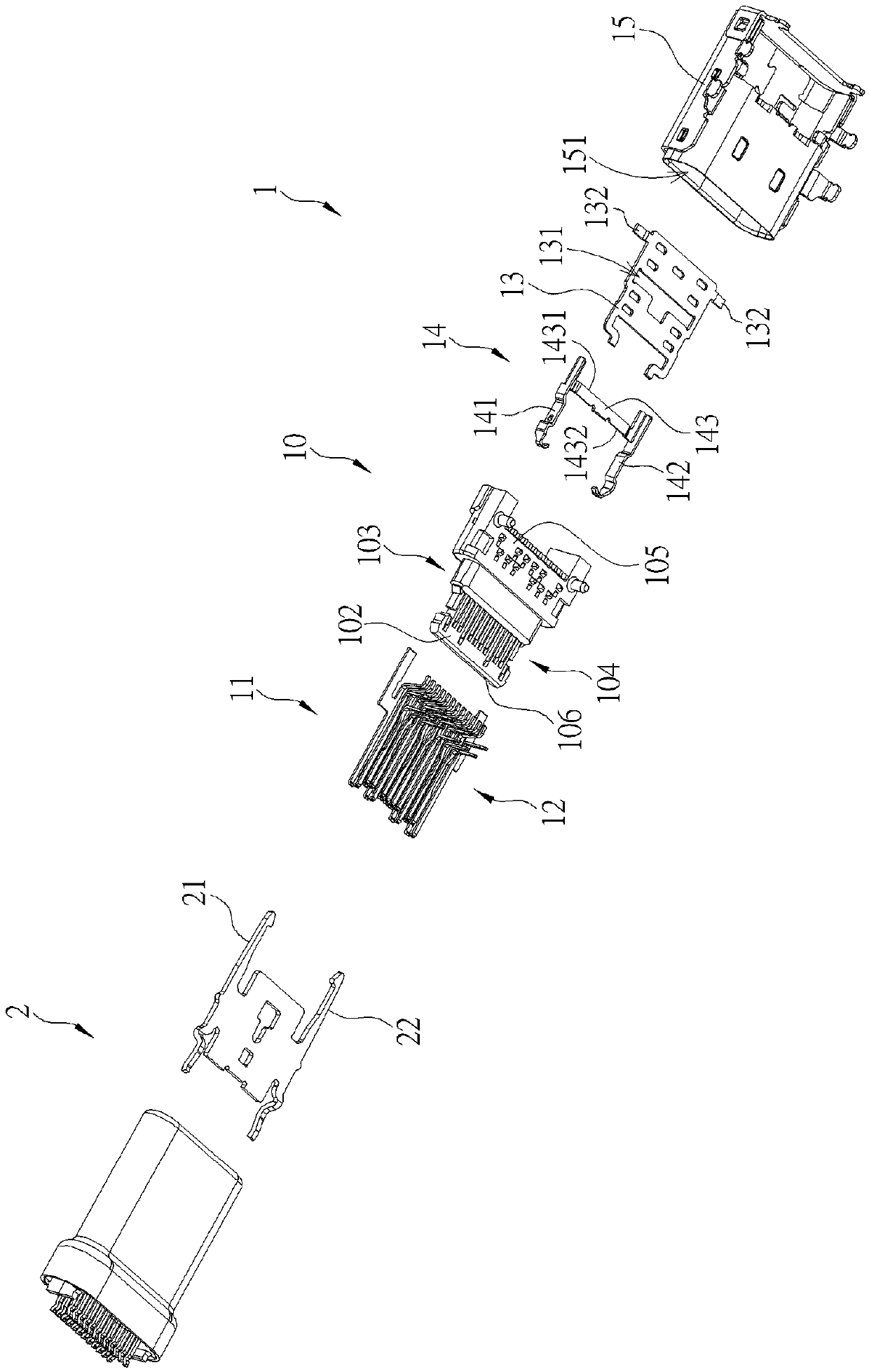
[0095] Please refer to Figures 1 to 3. Figure 1 is a schematic view of the appearance of a receptacle electrical connector 1 and a corresponding plug electrical connector 2 according to the first embodiment of the present invention. Figures 2 and 3 are diagrams of the present invention. An exploded view of some components of the socket electrical connector 1 and the corresponding plug electrical connector 2 in different viewing angles according to the first embodiment. As shown in Figures 1 to 3, the socket electrical connector 1 can be set on an electronic device (such as a computer host, a notebook computer or a mobile phone, etc.) A device supplies power or transmits a signal. The socket electrical connecto...


PUM


Abstract

The invention provides an electrical receptacle connector which comprises a rubber core seat, a first terminal group, a second terminal group, a middle metal sheet and a shielding assembly. The firstterminal group and the second terminal group are arranged in the rubber core seat and are respectively exposed out of two opposite sides of the rubber core seat; the middle metal sheet is arranged inthe rubber core seat and is positioned between the first terminal group and the second terminal group; the shielding assembly comprises a first sheet-shaped component and a second sheet-shaped component. The first sheet-shaped component and the second sheet-shaped component are at least partially embedded into the other two opposite sides of the rubber core base respectively, the first sheet-shaped component comprises a first step structure and a first contact part, and the second sheet-shaped component comprises a second step structure and a second contact part.

Description

technical field [0001] The invention relates to a socket electric connector, especially a socket electric connector which can prevent the wear and deformation of tongue pieces and avoid signal interference. Background technique [0002] Electrical connectors are indispensable components in electronic devices, allowing users to conveniently supply power or transmit signals to electronic devices. However, as the number of plugging and unplugging of the electrical connector increases, the tongue of the electrical connector is easily worn, deformed or even broken. Since the electrical socket connector is usually built directly on the main board of the electronic device, when the tongue of the electrical socket connector is worn or broken, the main board of the electronic device needs to be repaired or replaced at the same time, resulting in maintenance costs high. In addition, in response to the demand for massive data transmission, electrical connectors are gradually developi...

Claims


Application Information

Patent Timeline
Patent Type & Authority Applications(China)
IPC IPC(8): H01R13/502H01R13/6581H01R13/648
CPCH01R13/502H01R13/648H01R13/6581
Inventor 朱语晴刘阔正
Owner VITECK
Why Eureka
Try Eureka