

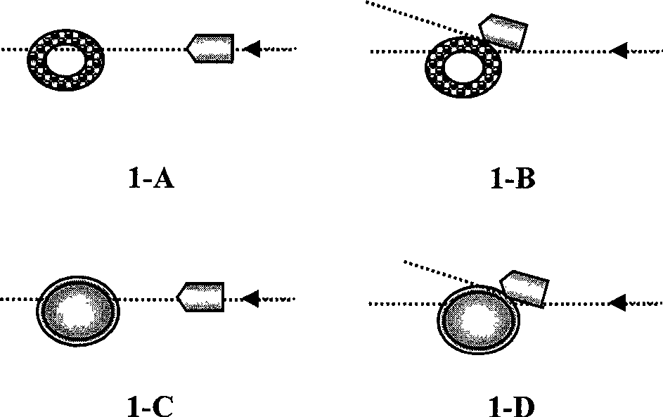
Preparation of ultra-high electron alloy capable of making injection body deviate
- Summary
- Abstract
- Description
- Claims
- Application Information
AI Technical Summary
Problems solved by technology
Method used
Image

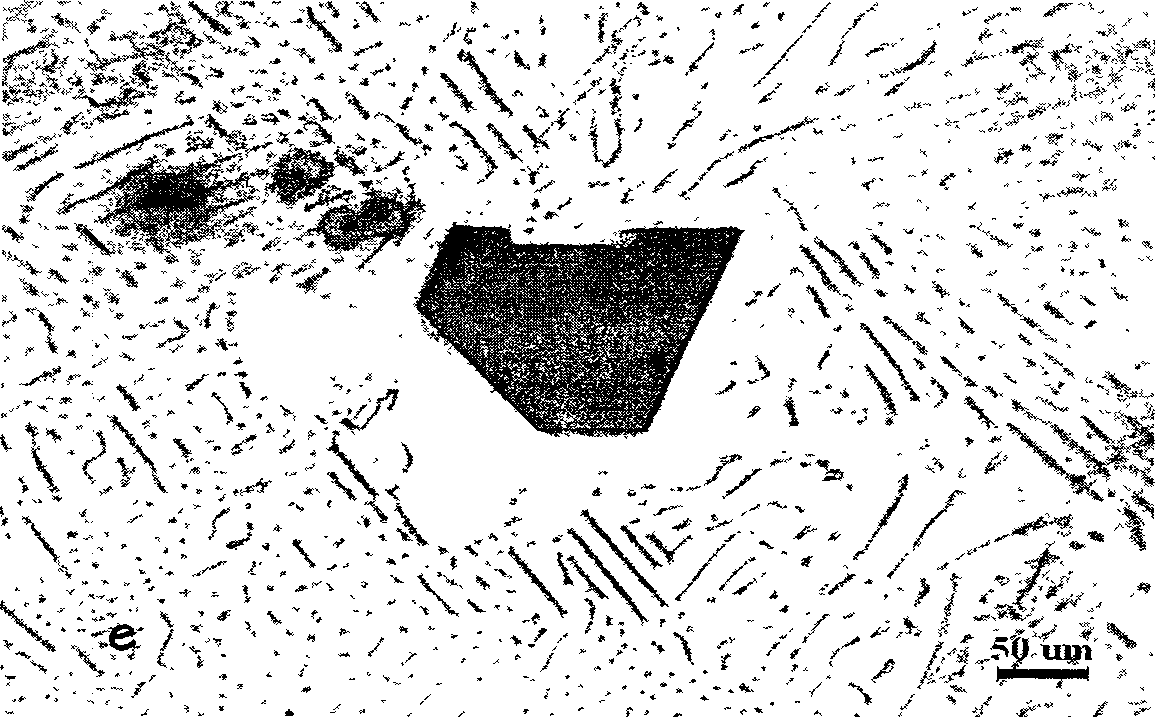
Examples
Embodiment 1
[0094] Add 68g of metal magnesium with a purity of 99.5% in the steel crucible, that is, W Mg = 68g. Then pour the analytically pure liquid KCl equal to the weight of the added magnesium onto the surface of the magnesium block. Induction heating melts magnesium and maintains the temperature at 790°C±3°C, which is also the in-situ synthesis temperature, expressed as T I-S =790°C±3°C. Then add 20g of expanded perlite particles, namely W V =20g, and stir with an iron stirring blade with a purity of 99.8%, until the perlite particles and liquid Mg undergo a reduction reaction and disappear completely. The composition of the perlite in terms of stable oxides is: SiO 2 72.5wt%, Al 2 o 3 13.5wt%, K 2 O is 4.25wt%, Na 2 O is 3.75wt%, CaO is 0.1wt%, Fe 2 o 3 It is 0.9wt%, MgO is 0.075wt%, H or O and other non-displaying substances are analyzed to be 4.925wt%, and the sum of the compositions of various component analytes constitutes 100%.
[0095] Then add 415g of metal alumi...
Embodiment 2
[0102] All the other are with embodiment 1. The difference is: ① raw material input quantity control conditions, such as the corresponding data in Table 1; ② temperature control conditions, such as the corresponding data in Table 2; ③ stirring time control conditions, such as the corresponding data in Table 3; ④ argon blowing condition control, such as Table 4 corresponding data; ⑤ alloy chemical composition analysis results, such as the corresponding data in Table 5; ⑥ determination results of hardness, compressive strength and injection trajectory deviation percentage, such as the corresponding data in Table 6.
Embodiment 3
[0104] All the other are with embodiment 1. The difference is: ① raw material input quantity control conditions, such as the corresponding data in Table 1; ② temperature control conditions, such as the corresponding data in Table 2; ③ stirring time control conditions, such as the corresponding data in Table 3; ④ argon blowing condition control, such as Table 4 corresponding data; ⑤ alloy chemical composition analysis results, such as the corresponding data in Table 5; ⑥ determination results of hardness, compressive strength and injection trajectory deviation percentage, such as the corresponding data in Table 6.
PUM
| Property | Measurement | Unit |
|---|---|---|
| yield strength | aaaaa | aaaaa |
| tensile strength | aaaaa | aaaaa |
| yield strength | aaaaa | aaaaa |
Abstract
Description
Claims
Application Information