Computerized flat knitting machine inlaid yarn nozzle transmission device

A transmission device, computerized flat knitting technology, applied in textile and papermaking, weft knitting, knitting and other directions, can solve problems such as affecting normal work, loosening of intarsia yarn feeders, affecting the stability of movement of intarsia yarn feeders, etc. The effect of expanding diversity and increasing the number of distributions

Inactive Publication Date: 2015-01-21
SHAOXING CITY YUEFA MACHINE +1
View PDF7 Cites 0 Cited by
  • Summary
  • Abstract
  • Description
  • Claims
  • Application Information

AI Technical Summary

Problems solved by technology

[0002] The existing computerized flat knitting machine's intarsia yarn feeder transmission device generally adopts two methods, one is driven by the intermediate connecting body connecting the front and rear heads on the machine head, and the structure is relatively complicated; the other is driven by a synchronous belt to drive the yarn The moving assembly of the nozzle is distributed on both sides of the guide rail of each shuttle, and the position adjustment range of the four guide rollers on the moving assembly of the intarsia yarn nozzle is relatively small
In this way, on the one hand, due to the uncertainty of parts processing accuracy and component assembly technology, the stability of the movement of the intarsia yarn feeder is affected; , making the intarsia yarn feeder loose during operation and affecting its normal work

Method used


Image

  • Computerized flat knitting machine inlaid yarn nozzle transmission device
  • Computerized flat knitting machine inlaid yarn nozzle transmission device
  • Computerized flat knitting machine inlaid yarn nozzle transmission device

Examples


Embodiment Construction

[0038] The preferred embodiments of the present invention will be further described in detail with reference to the accompanying drawings.

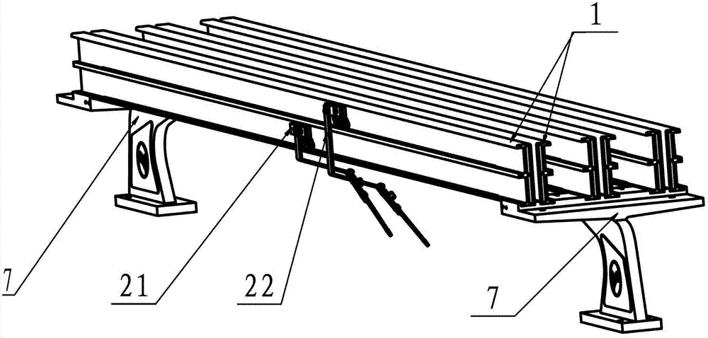
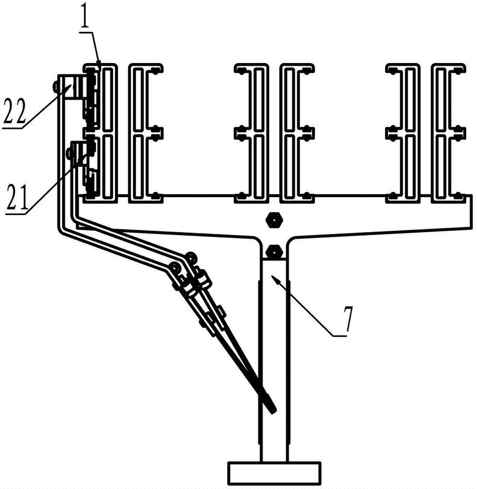
[0039] The main components included in the present invention are a shuttle guide rail assembly 1, and two groups of yarn feeder moving assemblies 21 and 22 installed on the shuttle guide rail assembly 1.

[0040] When the present invention is actually assembled, it is fixedly mounted on the left and right shuttle rail seats 7 of the machine, such as figure 1 As shown, the yarn feeder moving assemblies 21 and 22 are respectively installed on the same side of each group of shuttle guide rail assemblies 1, and are distributed up and down; every two shuttle guide rail assemblies 1 are arranged back-to-back, that is, two shuttle guide rail assemblies 1. Symmetrically arranged, the sides of the yarn feeder moving assemblies 21 and 22 are installed facing outward to form a pair, such as figure 1 , 2 shown. Multiple pairs of shuttle guide rail...


PUM


Abstract

The invention mainly discloses a computerized flat knitting machine inlaid yarn nozzle transmission device which comprises shuttle guide rail combined bodies and two sets of yarn nozzle moving combined bodies. The yarn nozzle moving combined bodies are mounted on an upper shuttle rail and a lower shuttle rail on a same side face of each shuttle guide rail combined body respectively. The two sets of yarn nozzle moving combined bodies are placed on the same side face of a same shuttle guide rail and are in upper-lower distribution, and the thickness of the shuttle guide rail is reduced, so that in limited front-rear space of a computerized flat knitting machine, distribution quantity of the shuttle guide rail and the total line number of yarn nozzles are increased, and diversity of machine fabric is expanded.

Description

technical field [0001] The invention relates to the technical field of computerized flat knitting machines, in particular to a transmission device for an intarsia yarn feeder of a computerized flat knitting machine. Background technique [0002] The intarsia yarn feeder transmission device on the existing computerized flat knitting machine generally adopts two methods, one is driven by the intermediate connecting body on the machine head connecting the front and rear machine heads, and the structure is relatively complicated; the other is driven by a synchronous belt to drive the yarn The moving assemblies of the nozzles are distributed on both sides of the guide rail of each shuttle, and the position adjustment range of the four guide rollers on the moving assemblies of the intarsia yarn feeders is relatively small. In this way, on the one hand, the stability of the movement of the intarsia yarn feeder is affected by the uncertainty of the machining accuracy of the parts an...

Claims


Application Information

Patent Timeline
Patent Type & Authority Patents(China)
IPC IPC(8): D04B15/96D04B15/80D04B15/70
Inventor 钱福海丁原章
Owner SHAOXING CITY YUEFA MACHINE
Why Eureka
Try Eureka