Test device of igniting tube

A test device and ignition tube technology, which is applied in the direction of combustion ignition, combustion method, lighting and heating equipment, etc., can solve the problems of insufficient test means and the inability to provide the test process, and achieve the effect of safety protection and avoiding danger

Active Publication Date: 2010-11-03
BYD CO LTD
View PDF5 Cites 3 Cited by
  • Summary
  • Abstract
  • Description
  • Claims
  • Application Information

AI Technical Summary

Problems solved by technology

[0004] The purpose of the present invention is to provide a low-cost, high-safety ignition tube testing device for the problems of insufficient testing means and the inability to provide safety protection during the testing process of the existing ignition tube testing device

Method used


Image

  • Test device of igniting tube
  • Test device of igniting tube
  • Test device of igniting tube

Examples


Embodiment Construction

[0024] The ignition tube testing device provided by the present invention will be further described in detail below in conjunction with the accompanying drawings.

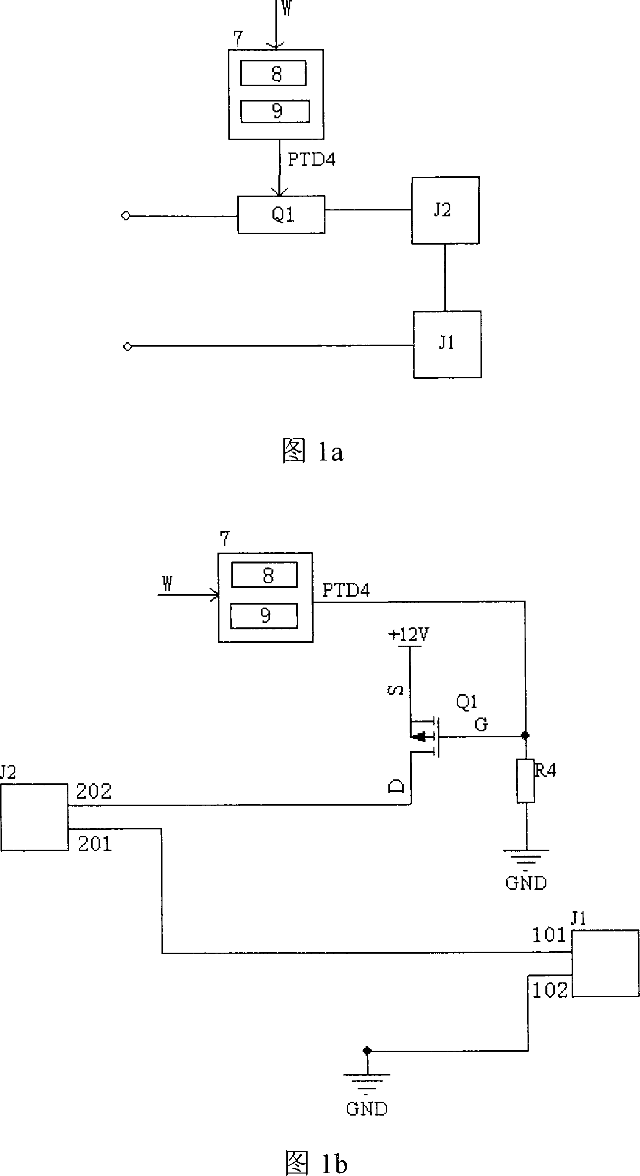
[0025] The test device provided by the present invention includes a first switch Q1, a load interface J2, an ignition tube interface J1 and a controller 7, one end of the first switch Q1 is connected in series to one end of the ignition tube interface J1 through the load interface J2, and the first The other end of the switch Q1 and the other end of the ignition tube interface J1 are respectively used to connect to the positive pole and the negative pole of the power supply, the controller 7 is connected to the control end of the first switch Q1, and the controller 7 is used to receive the starting signal and control The first switch Q1 is turned on, and the first switch Q1 is controlled to be turned off after a predetermined time.

[0026] like Figure 1a As shown, the controller 7 has a signal input terminal W, a...


PUM


Abstract

An igniter squib testing device comprises a first switch (Q1), a load interface (J2), an igniter squib interface (J1) and a controller (7), wherein, one end of the first switch (Q1) is connected with one end of the igniter squib interface (J1) in series by the load interface (J2), the other end of the first switch (Q1) and the other end of the igniter squib interface (J1) are respectively used for being connected with a positive pole and a negative pole of a power supply, and the controller (7) is connected with a control end of the first switch (Q1) and is used for receiving enabling signals, controlling the first switch (Q1) to close and controlling the first switch (Q1) to be cut off by preset time. The igniter squib testing device accurately controls the conduction time of an ignitionsquib, thus providing effective and safe protection for the test process of the ignition squib.

Description

technical field [0001] The invention relates to the field of current testing, in particular to a testing device for an ignition tube. Background technique [0002] The ignition tube is an ignition device that converts electrical energy into heat energy to cause an explosion. It has a minimum ignition current value and a maximum safety current value. It is triggered by introducing a current above the minimum ignition current value into the ignition tube and generating heat after a certain period of time. Explosion, and the current below the maximum safe current value into the ignition tube will not cause an explosion. The minimum firing current value and the maximum safe current value of the ignition tube are important parameters for correctly understanding the electrical characteristics of the ignition tube, and are also the main basis for designing the ignition tube and blasting network. Correctly mastering the test method of the minimum ignition current value and the maxi...

Claims


Application Information

Patent Timeline
Patent Type & Authority Patents(China)
IPC IPC(8): F23Q23/00
Inventor 宋豪杰徐波吴寒杰林承德
Owner BYD CO LTD
Why Eureka
Try Eureka