Control method of video camera synchronous LED flash light compensation

A control method and camera technology, which is applied in the field of camera supplementary light, can solve the problems that the power supply system cannot provide high-power lighting power supply, etc., and achieve the effects of prolonging life, reducing working temperature, and reducing power consumption

Active Publication Date: 2009-04-22
SHANGHAI YAO WEI GROUP IND
View PDF0 Cites 32 Cited by
  • Summary
  • Abstract
  • Description
  • Claims
  • Application Information

AI Technical Summary

Problems solved by technology

[0007] But for some applications, the power supply system cannot provide high-power lighting power supply

Method used


Image

  • Control method of video camera synchronous LED flash light compensation
  • Control method of video camera synchronous LED flash light compensation

Examples


Embodiment Construction

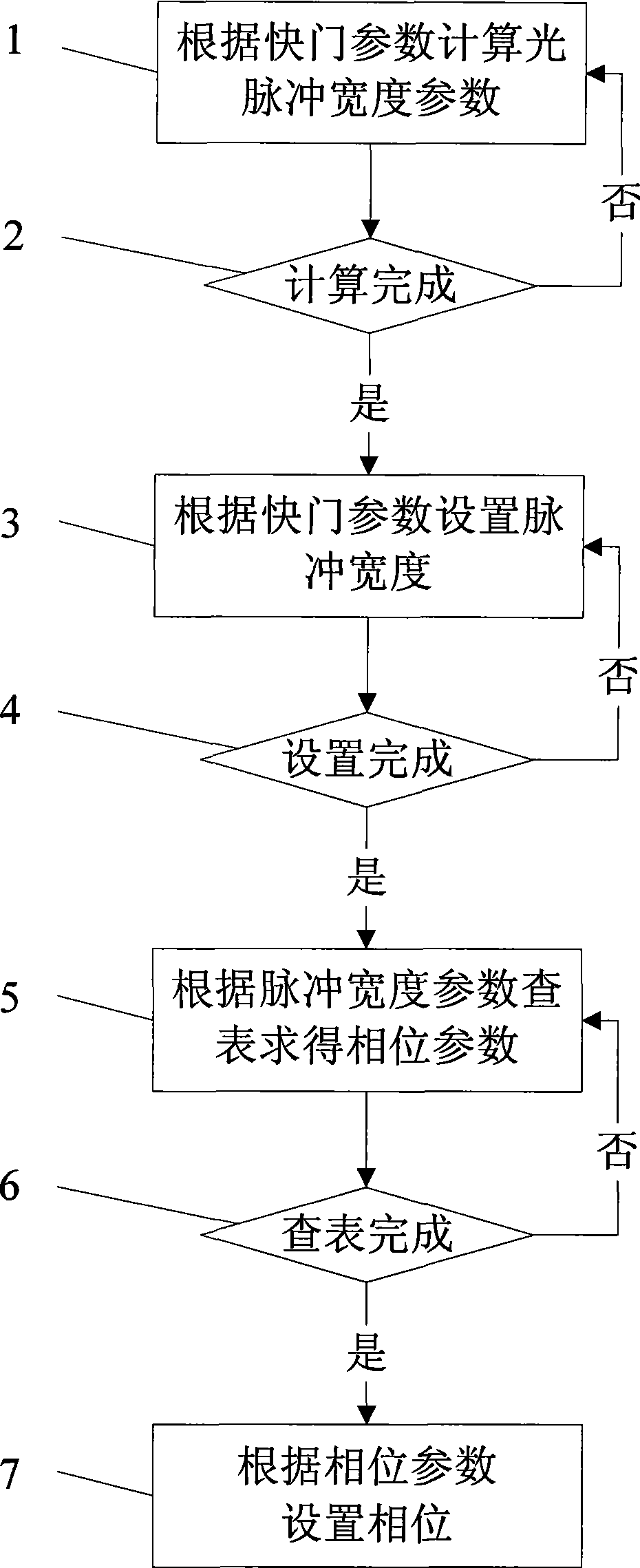
[0039] Such as figure 1 As shown, in a control method for camera synchronous LED flash supplementary light, step 1 is the initial step, and the light pulse width parameter is calculated according to the shutter parameter; in step 2, whether the calculation is completed is detected, and if the detection result is no, then Return to step 1; if the detection result in step 2 is yes, then in step 3, set the pulse width according to the shutter parameter; in step 4, check whether the setting is complete, if the detection result is no, then return to step 3; if step The result of detection in 4 is yes, then in step 5, obtain the phase parameter according to the pulse width parameter look-up table; If the result of the detection is yes, then in step 7, set the phase according to the phase parameter.

[0040] The luminous efficiency of LED light sources is higher than that of incandescent light sources, fluorescent light sources, and ordinary energy-saving light sources. At the same...


PUM


Abstract

The invention relates to a control method for a camera synchronous LED flash and fill-in light, which comprises the following steps: a width parameter of an optical pulse is calculated according to a shutter parameter; whether the calculation is completed or not is detected; if yes, the pulse width is set up according to the shutter parameter; whether the setting is finished is detected; if yes, a phase position parameter is obtained by searching a table according to the pulse width; whether the table search is finished is detected; if yes, the phase position is set up according to the phase parameter. Compare with the prior art, in the invention, LED light source flash pulse and shutter are synchronous, thus providing light source with high speed flash for a camera and reducing the energy consumption in the premise of guaranteeing light filling; by this means, the working temperature of the LED is reduced and the service life of the LED is prolonged. When a person faces the camera and feels the illumination of the light source is lower in the premise of guaranteeing image quality, the person to be shot has no lighting glaring sense, thus behaving natural in the shooting process.

Description

technical field [0001] The invention relates to a method for supplementary light of a camera, in particular to a method for controlling synchronous LED flash supplementary light of a camera. Background technique [0002] In a low-light environment, ordinary cameras (non-low-light cameras, non-ultra-low-light (starlight) cameras) cannot image or the image is very noisy and the image quality is poor. [0003] In order to make up for the lack of light of ordinary cameras in low-light environments, auxiliary light sources are generally used to illuminate the area shot by the camera. This auxiliary light source is often used for continuous lighting with constant brightness incandescent lamps or constant brightness white LED continuous lighting. [0004] Auxiliary supplementary light sources are mostly used indoors or semi-indoor and semi-outdoor, such as bank office areas, ATM lighting in 24-hour self-service banks, indoor and outdoor corridors in office buildings, elevator room...

Claims


Application Information

Patent Timeline
Patent Type & Authority Applications(China)
IPC IPC(8): G03B15/05H04N5/225H04N5/232H04N5/235
Inventor 彭树林姚薇
Owner SHANGHAI YAO WEI GROUP IND
Why Eureka
Try Eureka