Mobile communication apparatus with current-limiting charge function

A mobile communication device and current-limited charging technology, applied in circuit devices, battery circuit devices, electric vehicles, etc., can solve problems such as poor charging performance and inability to charge, and achieve safe or fast charging performance, optimal charging performance, and avoidance of The effect of charging current loss on mobile communication devices or poor charging efficiency

Inactive Publication Date: 2009-04-22
INVENTEC(NANJING) TECH CO LTD
View PDF0 Cites 31 Cited by
  • Summary
  • Abstract
  • Description
  • Claims
  • Application Information

AI Technical Summary

Problems solved by technology

However, when charging with a charging current not greater than 500 milliamperes, the energy storage unit 15 of the mobile communication device 1 cannot be quickly charged to a sufficient capacity through a single charging circuit 13, resulting in poor charging performance.

Method used


Image

  • Mobile communication apparatus with current-limiting charge function
  • Mobile communication apparatus with current-limiting charge function
  • Mobile communication apparatus with current-limiting charge function

Examples


no. 1 example

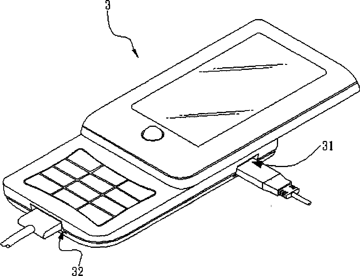
[0050] Please refer to image 3 and Figure 4 As shown, a mobile communication device 3 with a current-limited charging function according to the first embodiment of the present invention includes a first power connector 31, a second power connector 32, a first charging circuit 33, and a second charging circuit 33. The circuit 34 and an energy storage unit 35 . The first power connector 31 is electrically connected with a first power supply unit P1 to receive the electric energy input by the first power supply unit P1 , and then transmit the electric energy to the first charging circuit 33 to charge the energy storage unit 35 . The second power connector 32 is electrically connected to a second power supply unit P2 to receive the electric energy input by the second power supply unit P2 , and then transmit it to the second charging circuit 34 to charge the energy storage unit 35 . Wherein, the currents of the first power supply unit P1 and the second power supply unit P2 are ...

no. 2 example

[0063] Please refer to Image 6 and Figure 7 As shown, a mobile communication device 3' with a current-limited charging function according to the second embodiment of the present invention is the same as the first embodiment (such as Figure 3 to Figure 5 ) The mobile communication device 3 differs in that: the mobile communication device 3' only has a single power connector 30, which can be used to electrically connect to a USB power supply unit and a normal standard power supply unit. and based on Figure 7 It can be seen from the shown electrical connection relationship that the power connector 30 is electrically connected to the first charging circuit 33 and the second charging circuit 34 respectively, and is electrically connected to the energy storage unit 35 through the first charging circuit 33 and the second charging circuit 34. sexual connection.

[0064] Wherein, the maximum charging current that the first charging circuit 33 can bear is not greater than a set v...


PUM


Abstract

The present invention relates to a mobile communication device with current-limited charging function, which consists of an energy storage unit, a first power connector, a first charging circuit, a second power connector and a second charging circuit. The first charging circuit is electrically connected with the first power connector and the energy storage unit and the maximum current of the first charging circuit is not more than a set value; the second charging circuit is electrically connected with the second power connector and the energy storage unit and the maximum current of the second charging circuit is more than the set value. The mobile communication device with current-limited charging function adopts the structure; therefore, when the charging is carried out through different chargers, the mobile communication device can start the corresponding charging circuit according to the current range provided by the charger so as to prevent different charging currents from damaging the mobile communication device.

Description

technical field [0001] The present invention relates to the technical field of mobile communication, in particular to the technical field of charging mechanisms for mobile communication devices, in particular to a mobile communication device with a current-limited charging function. Background technique [0002] Please refer to figure 1 and figure 2 As shown, general portable electronic devices such as mobile communication devices, mobile personal assistants, mobile audio-visual devices, etc., are used to charge the energy storage unit. The device 1 is electrically connected to the external power supply unit P, and the common external power supply unit P is usually a charging stand, a travel charger or a car charger, etc.; the other is a Universal Serial Bus (USB) power connector 11, which is also arranged on the mobile communication device 1, but the external power supply unit electrically connected to the USB power connector 11 is the computer 2, and is electrically con...

Claims


Application Information

Patent Timeline
Patent Type & Authority Applications(China)
IPC IPC(8): H02J7/00H01M10/44
CPCY02E60/12Y02E60/10
Inventor 周继华许庆欣朱于乐
Owner INVENTEC(NANJING) TECH CO LTD
Why Eureka
Try Eureka