Segmentation iron core and coiling method for motor

A kind of iron core, winding technology, is used in the field of stator in the transmission permanent magnet synchronous motor, which can solve problems such as affecting the fullness of the slot, the coil sliding phenomenon, and the unable to be completely arranged. The effect of slot fullness

Inactive Publication Date: 2009-04-22
SHANGHAI HITACHI ELECTRICAL APPLIANCES CO LTD
View PDF0 Cites 8 Cited by
  • Summary
  • Abstract
  • Description
  • Claims
  • Application Information

AI Technical Summary

Problems solved by technology

[0003] At present, when the split core winding process is used, due to the relationship between the groove shape, the coils will slide at the position A in the diagram during winding, so they cannot be completely arranged neatly and thus affect the maximization of the slot fullness rate.

Method used


Image

  • Segmentation iron core and coiling method for motor
  • Segmentation iron core and coiling method for motor
  • Segmentation iron core and coiling method for motor

Examples


Embodiment Construction

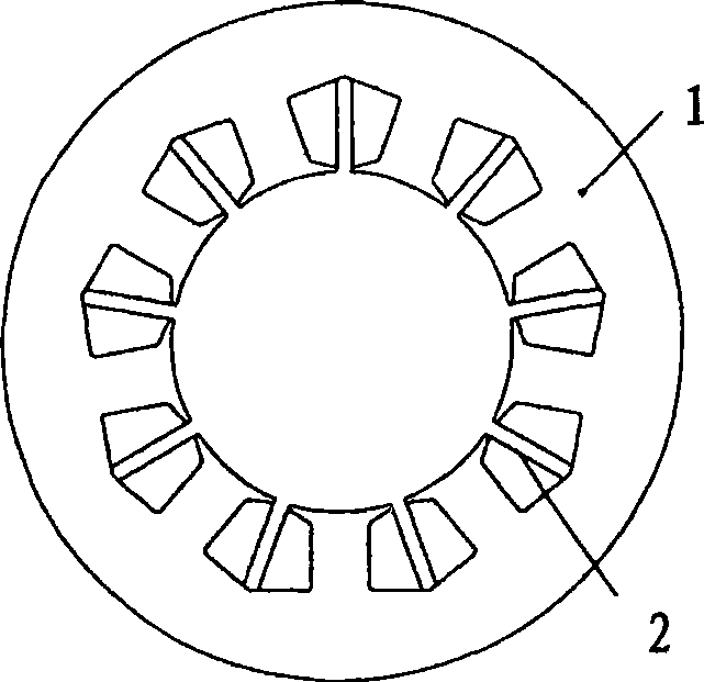
[0019] Such as figure 1 As shown, in the centralized winding motor where the winding is directly performed at the position of the tooth part 1 of the existing motor, since the stator core is an integral structure, a space 2 should be reserved during the winding process of the motor. Since this space cannot be used, the affect the motor efficiency.

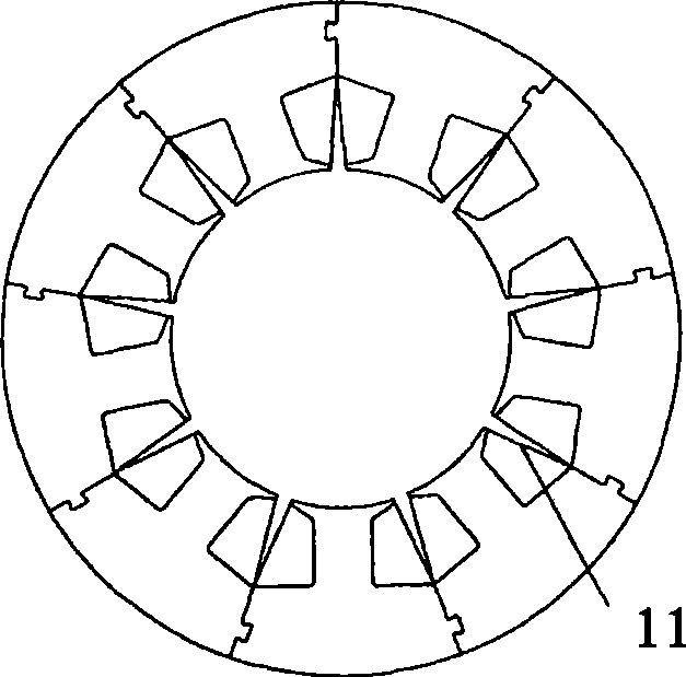
[0020] Figure 2A It shows the schematic diagram of the existing split iron core. At present, there are the following problems: a certain distance is reserved between adjacent teeth at the slot structure. At this time, due to the insulation distance of the opening, a part of the slot space 11 cannot be wound around. Wire.

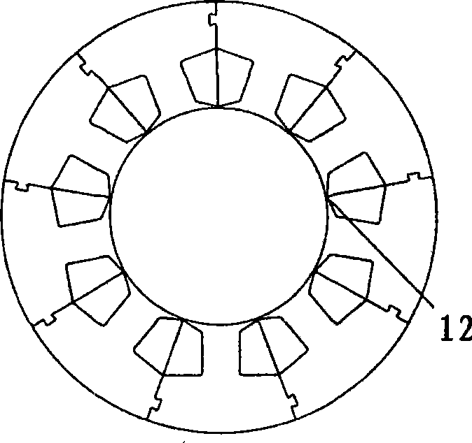
[0021] Figure 2B It shows another schematic diagram of the existing split iron core. At present, there are the following problems: due to the contact between adjacent teeth, part of the stator and rotor magnetic flux passes through the contact part 12 to form a closed loop without connecting with the stator ...


PUM


Abstract

The present invention relates to a block for a stator segmenting iron core in a compressor motor. Wherein, the gear top part and the gear root part of the block are parallel with each other so as to ensure the groove shape to constitute a complete trapezoid; the block is designed with a mortise structure so as to connect the adjacent blocks.

Description

technical field [0001] The invention relates to a motor stator, in particular to a stator of a variable speed permanent magnet synchronous motor used for a compressor. Background technique [0002] In the stator core of the compressor motor with integral structure, the concentrated winding method is adopted, so it is necessary to leave an empty slot larger than the width of the winding needle in the wire slot, thus reducing the winding density and the slot fullness of the wire slot. In order to improve the slot full rate, the split iron core winding process is generally used at present. Firstly, the stator is unfolded, and the coil is wound on the teeth, and then the bending mouth is put together and restored to a circular shape by pressure shaping. [0003] At present, when the split core winding process is used, due to the relationship between the slot shape, the coils will slide at the position A shown in the figure during winding, so they cannot be completely arranged ne...

Claims


Application Information

Patent Timeline
Patent Type & Authority Applications(China)
IPC IPC(8): H02K1/14H02K3/18H02K15/095
Inventor 王鲁
Owner SHANGHAI HITACHI ELECTRICAL APPLIANCES CO LTD
Why Eureka
Try Eureka