Permanent magnet motor topology construction method based on working magnetic field harmonic orientation, and motor

A permanent magnet motor and magnetic field harmonic technology, applied to synchronous motors with stationary armature and rotating magnets, magnetic circuit shape/style/structure, magnetic circuit, etc., can solve the difficult to achieve motor topology innovation, torque Density, design process irregularity, rigidity and other problems, to achieve the effect of improving torque output capability, wide application range, and improving slot full rate

Active Publication Date: 2021-02-26
HUAZHONG UNIV OF SCI & TECH
View PDF10 Cites 8 Cited by
  • Summary
  • Abstract
  • Description
  • Claims
  • Application Information

AI Technical Summary

Problems solved by technology

However, at present, when designing motors, the design of permanent magnet rotors, stators, armature windings and other structures in the motor has been constrained by the traditional topology framework. The improvement of performance needs to be achieved through repeated optimization of structural parameters, and the design process is irregular. , there is a strong contingency, it is difficult to realize the topology innovation of the motor and the improvement of the torque density

Method used


Image

  • Permanent magnet motor topology construction method based on working magnetic field harmonic orientation, and motor
  • Permanent magnet motor topology construction method based on working magnetic field harmonic orientation, and motor
  • Permanent magnet motor topology construction method based on working magnetic field harmonic orientation, and motor

Examples


Embodiment Construction

[0031] In order to make the object, technical solution and advantages of the present invention clearer, the present invention will be further described in detail below in conjunction with the accompanying drawings and embodiments. It should be understood that the specific embodiments described here are only used to explain the present invention, not to limit the present invention. In addition, the technical features involved in the various embodiments of the present invention described below can be combined with each other as long as they do not constitute a conflict with each other.

[0032] In the present invention, the terms "first", "second" and the like (if any) in the present invention and drawings are used to distinguish similar objects, and are not necessarily used to describe a specific order or sequence.

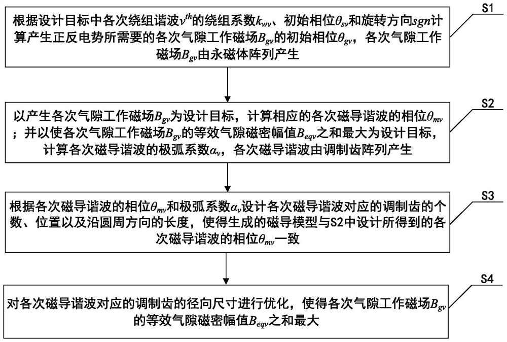
[0033] figure 1 It is a flow chart of a permanent magnet motor topology construction method based on working magnetic field harmonic orientation in an embodiment ...


PUM


Abstract

The invention discloses a permanent magnet motor topology construction method based on working magnetic field harmonic orientation, and a motor, belonging to the technical field of permanent magnet motors. The method comprises the following steps: calculating the initial phase Bgv of each air gap working magnetic field Bgv needed by the generation of positive and negative potentials according to the parameters of each winding harmonic wave vth in a design target; calculating the phase theta mv and the polar arc coefficient alpha v of each corresponding magnetic conductance harmonic wave by taking the generation of Bgv and the maximization of the sum of equivalent air gap flux density amplitudes Beqv of the Bgv as a design target; designing the number and positions of modulation teeth corresponding to the magnetic conductance harmonic waves of each time and the length in a circumferential direction according to the theta mv and the alpha v so as to allow a generated magnetic conductancemodel to be consistent with the phase theta mv of the magnetic conductance harmonic waves of each time designed in S2; and optimizing the radial size of the modulation tooth corresponding to each magnetic conductance harmonic wave so as to allow the sum of the equivalent air gap flux density amplitudes Beqv of each air gap working magnetic field Bgv to be maximum. According to the invention, directional structure of a motor modulation tooth array is realized, the motor can generate multiple working magnetic fields, and the torque output capability of the motor is effectively improved.

Description

technical field [0001] The invention belongs to the technical field of permanent magnet motors, and more specifically relates to a permanent magnet motor topology construction method and motor based on harmonic orientation of a working magnetic field. Background technique [0002] Since the first electric motor came out in the 19th century, electric motors have become an indispensable industrial category supporting modern human society. Motors are widely used in all aspects of the national economy, ranging from hydroelectric generators with a stand-alone capacity of several thousand megawatts to micro-motors as small as a few microwatts. With the rising wave of electrification and the continuous development of manufacturing industries such as industrial robots, chip manufacturing, and CNC machine tools, motors play a more important role. At the same time, higher requirements are put forward for the performance and quality of motors such as torque density, response speed, and...

Claims


Application Information

Patent Timeline
Patent Type & Authority Applications(China)
IPC IPC(8): H02K21/22H02K21/02H02K1/14H02K1/27
CPCH02K21/22H02K21/024H02K1/146H02K1/2786H02K2201/03H02K2213/03H02K1/2791H02K29/03
Inventor 李大伟房莉任翔曲荣海
Owner HUAZHONG UNIV OF SCI & TECH
Why Eureka
Try Eureka