Synchronous electric main shaft acceleration strong magnetic control method for variable-load superhigh-speed grinding

A technology of ultra-high-speed grinding and control method, which is applied in the direction of electronic commutation motor control, motor generator control, control system, etc., which can solve the problems of lack of tracking ability, difficulty in constant power expansion, and difficulty in adapting to variable loads.

Active Publication Date: 2016-07-13
HUNAN UNIV
View PDF6 Cites 6 Cited by
  • Summary
  • Abstract
  • Description
  • Claims
  • Application Information

AI Technical Summary

Problems solved by technology

[0004] Using the existing maximum torque current ratio MTPA (MaximumTorqueperAmpere, MTPA) or i d =0 Problems in the control method: (1) constant power expansion is difficult
When the rated speed of the motor is lower than the working speed, MTPA control is used for constant power speed regulation, because i d = 0, the armature does not produce negative magnetic field to offset the permanent magnet flux linkage, the air gap flux is constant, and the back electromotive force is proportional to the speed, which can easily cause the back electromotive force to be too large, exceeding the voltage limit that the driver can withstand, thus causing the driver Automatic alarm trip, the speed is difficult to reach the working speed required for ultra-high-speed grinding
(2) No reluctance torque, limited output
because i d = 0, the electromagnetic torque of the motor is only generated by the permanent magnet flux linkage without the reluctance torque item, resulting in the restriction of the output torque capability, and it is difficult to resist variable load ultra-high speed grinding
Moreover, the rated point of the motor is set at the working point, so there is no need for constant power control and speed regulation, only MTPA or constant torque control speed regulation is required, and the speed can be raised to the working speed required by ultra-high-speed grinding. However, due to the motor rated The speed is greatly increased, and the volume will be greatly reduced under the same rated power. The space of the motor is limited, and the rigidity of the shaft system is difficult to guarantee, which will inevitably affect the grinding accuracy.
[0005] Existing problems in adopting the existing field weakening control: (1) The torque characteristic of the motor is reduced, and the output is limited
High-speed magnetic field weakening leads to a decrease in the torque characteristics of the motor
On the one hand, in the state of high-speed rotation, the mechanical electromagnetic loss of the motor consumes part of the power; on the other hand, the weakening of the magnetic field makes the electromagnetic torque generated by the permanent magnet flux linkage gradually weakened.
Due to the decrease of motor torque characteristics and limited output, it is difficult to adapt to the needs of ultra-high-speed grinding conditions with variable loads
(2) Slow dynamic response of motor torque
Due to the hard torque characteristics of the motor, coupled with the coupling effect of motor parameter changes and system parameters, the torque dynamic response is slow and the tracking ability is lacking, which will inevitably affect the stability of the torque speed
(3) The motor current is large, which may easily cause the controller to saturate and stall synchronously with the motor
In view of the above reasons, the use of magnetic field weakening control has the limitation that it is difficult to balance grinding efficiency, grinding quality and grinding accuracy at the same time.

Method used


Image

  • Synchronous electric main shaft acceleration strong magnetic control method for variable-load superhigh-speed grinding
  • Synchronous electric main shaft acceleration strong magnetic control method for variable-load superhigh-speed grinding
  • Synchronous electric main shaft acceleration strong magnetic control method for variable-load superhigh-speed grinding

Examples


Embodiment Construction

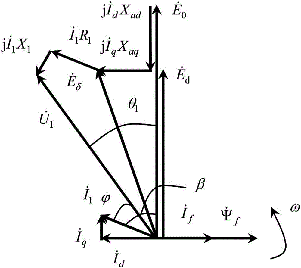
[0043] In the following, the synchronous motorized spindle for variable load ultrahigh speed grinding of the present invention will be added on the basis of the traditional constant magnetic (MTPA) control method + "weakening field" control method for the synchronous motorized spindle for variable load ultrahigh speed grinding. Taking the jerk control ("strong magnet" control method) as an example, the synchronous motor spindle jerk control method for variable load ultra-high-speed grinding of the present invention will be further described in detail.

[0044] The "strong field" control of permanent magnet synchronous motor spindle jerk is actually the reverse control process of field weakening control. To clarify the "strong magnetic" control principle, we must first clarify the "weak magnetic" control principle, and its principles can be found in figure 1 ,in, is the effective value of the no-load back EMF of each phase generated by the permanent magnetic air-gap fundament...


PUM


Abstract

The invention discloses a synchronous electric main shaft acceleration strong magnetic control method for variable-load superhigh-speed grinding, and the method comprises the steps: obtaining a d-axis current expected instruction value and a q-axis current expected instruction value of a synchronous electric main shaft in a closed-loop manner, and obtaining voltage expected instruction values at all phases in a three-phase stationary coordinate system; enabling error signals between the voltage expected instruction values at all phases in the three-phase stationary coordinate system and the action value of voltages at all phases to serve as the control signals of power switch IGBTs at all phases, carrying out the vector control of the actual output currents of a PWM Inverter driver at all phases; continuously increasing the q-axis current expected instruction value, and reducing the d-axis current expected instruction value; and enabling the internal power factor angle beta of the motor to be reduced continuously. The method is good in motor torque characteristics, is high in grinding efficiency, is high in dynamic response of motor torque speed, is good in robustness, is high in grinding quality and precision, is small in motor current, can effectively prevent a controller from being saturate, prevents a motor from stalling and being out of control, is high in efficiency, and saves energy.

Description

technical field [0001] The invention relates to ultra-high-speed grinding processing technology, in particular to a synchronous electric spindle acceleration strong magnetic control method for variable-load ultra-high-speed grinding. Background technique [0002] Ultra-high-speed grinding is a very challenging and efficient precision machining technology in the field of advanced manufacturing. It is the focus and frontier of the world's equipment manufacturing industry and industrialization competition. It has a wide range of uses in the efficient grinding of parts. [0003] Variable load ultra-high-speed grinding is a normal machining process. For example, during the grinding of non-circular contour parts, the grinding load changes continuously with the workpiece corner. In order to ensure the contour accuracy and surface quality of the ground workpiece, it is usually necessary to reduce the rotation speed or feed rate of the workpiece, resulting in a significant reduction...

Claims


Application Information

Patent Timeline
Patent Type & Authority Applications(China)
IPC IPC(8): H02P21/16
Inventor 吕浪熊万里
Owner HUNAN UNIV
Why Eureka
Try Eureka