Asymmetric hybrid magnetic pole type permanent magnet motor

A hybrid magnetic pole, permanent magnet motor technology, applied in the direction of magnetic circuit, electric components, electrical components, etc., can solve the problem of low utilization rate of torque components, and achieve the effect of reducing distortion rate, increasing ratio, and improving utilization rate.

Active Publication Date: 2019-10-11
SOUTHEAST UNIV
View PDF6 Cites 6 Cited by
  • Summary
  • Abstract
  • Description
  • Claims
  • Application Information

AI Technical Summary

Problems solved by technology

[0005] Purpose of the invention: The purpose of the invention is to provide an asymmetrical mixed magnetic pole type permanent magnet motor that can effectively solve the defect of low utilization rate of the torque component of the traditional built-in permanent magnet motor

Method used


Image

  • Asymmetric hybrid magnetic pole type permanent magnet motor
  • Asymmetric hybrid magnetic pole type permanent magnet motor
  • Asymmetric hybrid magnetic pole type permanent magnet motor

Examples


Embodiment Construction

[0026] The technical solution of the present invention will be further described below in conjunction with the accompanying drawings.

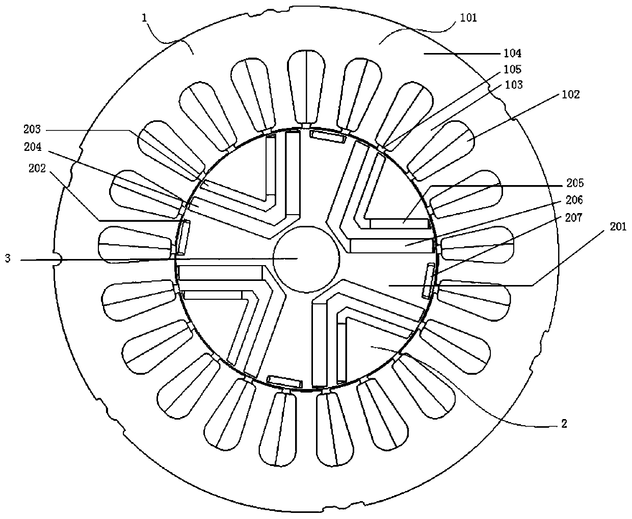
[0027] Such as figure 1 and figure 2 As shown, an asymmetric mixed magnetic pole permanent magnet motor of the present invention includes a casing, a stator 1, a rotor 2 and a rotating shaft 3, and the stator 1, rotor 2 and rotating shaft 3 are all arranged in the inner casing. The rotor 2 is pierced and fixed on the rotating shaft 3 , the stator 1 is arranged outside the rotor 2 , and there is an air gap between the stator 1 and the rotor 2 .

[0028] The stator 1 of the present invention comprises a stator core 101 and a three-phase armature winding 102, the stator core 101 comprises a stator tooth 103, a stator yoke 104 and a stator slot 105, one end of the stator tooth 103 is close to the rotor 2, and the stator tooth 103 is far away from the rotor 2 One end is connected by a stator yoke 104 , and a stator slot 105 is formed between adj...


PUM


Abstract

The invention discloses an asymmetric hybrid magnetic pole type permanent magnet motor. The asymmetric mixed magnetic pole type permanent magnet motor comprises a stator and a rotor, wherein the stator and the rotor are arranged in a sleeved mode inside and outside, and an air gap is formed between the stator and the rotor; the stator comprises a stator iron core and a three-phase armature winding; the rotor comprises a rotor yoke and a plurality of permanent magnet unit structures uniformly distributed on the rotor yoke in the circumferential direction; each permanent magnet unit structure comprises a multilayer magnetic barrier structure, a linear air magnetic barrier positioned on the outer side of the multilayer magnetic barrier structure, and built-in permanent magnets which are arranged in the multilayer magnetic barrier structure and the linear air magnetic barrier separately, wherein the circumferential angle corresponding to the multilayer magnetic barrier structure is alpha s, the circumferential angle corresponding to the linear air magnetic barrier is beta s, and the alpha s plus beta s is equal to 90 degrees. According to the permanent magnet motor, under the premise of a certain usage number of the permanent magnets, the permanent magnet torque and the magnetic resistance torque component can reach the maximum value at a close current angle based on the asymmetricdistribution of the permanent magnets, the torque component utilization rate is increased, and the torque output capability is improved.

Description

technical field [0001] The invention relates to a permanent magnet motor, in particular to an asymmetric mixed magnetic pole type permanent magnet motor. Background technique [0002] With the deterioration of the ecological environment and the exhaustion of global energy sources, vigorously developing the new energy automobile industry has become a key measure related to the development of the national economy. As users' demand for electric vehicles continues to increase, built-in permanent magnet synchronous motors (Permanent Magnet Synchronous Machine, PMSM) are widely used in the field of electric vehicles because of their high power density, high efficiency and better control accuracy, including Toyota Prius , Honda Insight and other models. [0003] However, the traditional built-in permanent magnet motor has a lot of permanent magnet flux leakage, and the utilization rate is not high. At the same time, due to the high price of rare earth permanent magnet materials, t...

Claims


Application Information

Patent Timeline
Patent Type & Authority Applications(China)
IPC IPC(8): H02K1/27H02K1/16H02K3/28
CPCH02K1/165H02K1/2753H02K3/28H02K2201/06H02K2213/03
Inventor 阳辉王伟嘉林鹤云李亚
Owner SOUTHEAST UNIV
Why Eureka
Try Eureka