
Internal tricyclic decelerator

A technology of reducer and ring plate, applied in the direction of gear transmission, belt/chain/gear, mechanical equipment, etc., can solve the problems of unbalanced additional torque, poor reliability of crank structure, and low life of ring plate bearing, etc. The effect of widening span, product application and improving torque output capability

Inactive Publication Date: 2008-02-06
北京瑞德信通用机械设备制造有限公司
View PDF0 Cites 6 Cited by
  • Summary
  • Abstract
  • Description
  • Claims
  • Application Information

AI Technical Summary

Problems solved by technology

However, this kind of crank type reducer with small tooth difference has problems such as poor rigidity of the combined frame, small load capacity, poor reliability of the crank structure, unbalanced additional torque caused by centrifugal force, and low service life of the ring plate bearing.
Some other circular translation crank type reducers with small tooth difference in the prior art adopt the technical scheme of combining the planetary small tooth difference gear mechanism and the cycloidal pin wheel, but the disadvantage of adopting this technical scheme is that the cycloidal pin There is sliding friction in the wheel transmission, so the efficiency of the reducer is low, and the shaft is easy to cut

Method used


Image

  • Internal tricyclic decelerator
  • Internal tricyclic decelerator
  • Internal tricyclic decelerator

Examples


Embodiment Construction

[0024] The specific implementation manner of the present invention will be described in detail below in conjunction with the accompanying drawings.

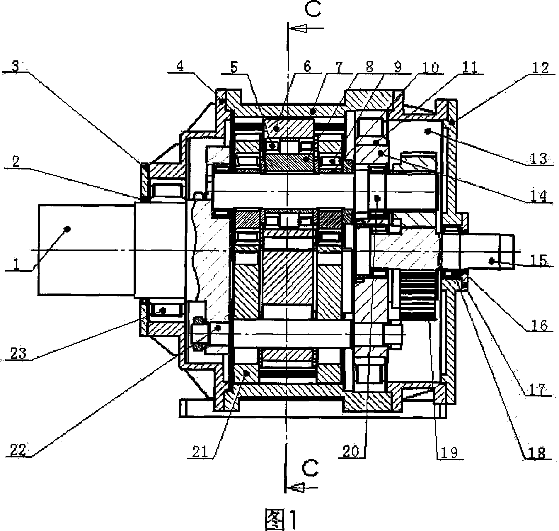
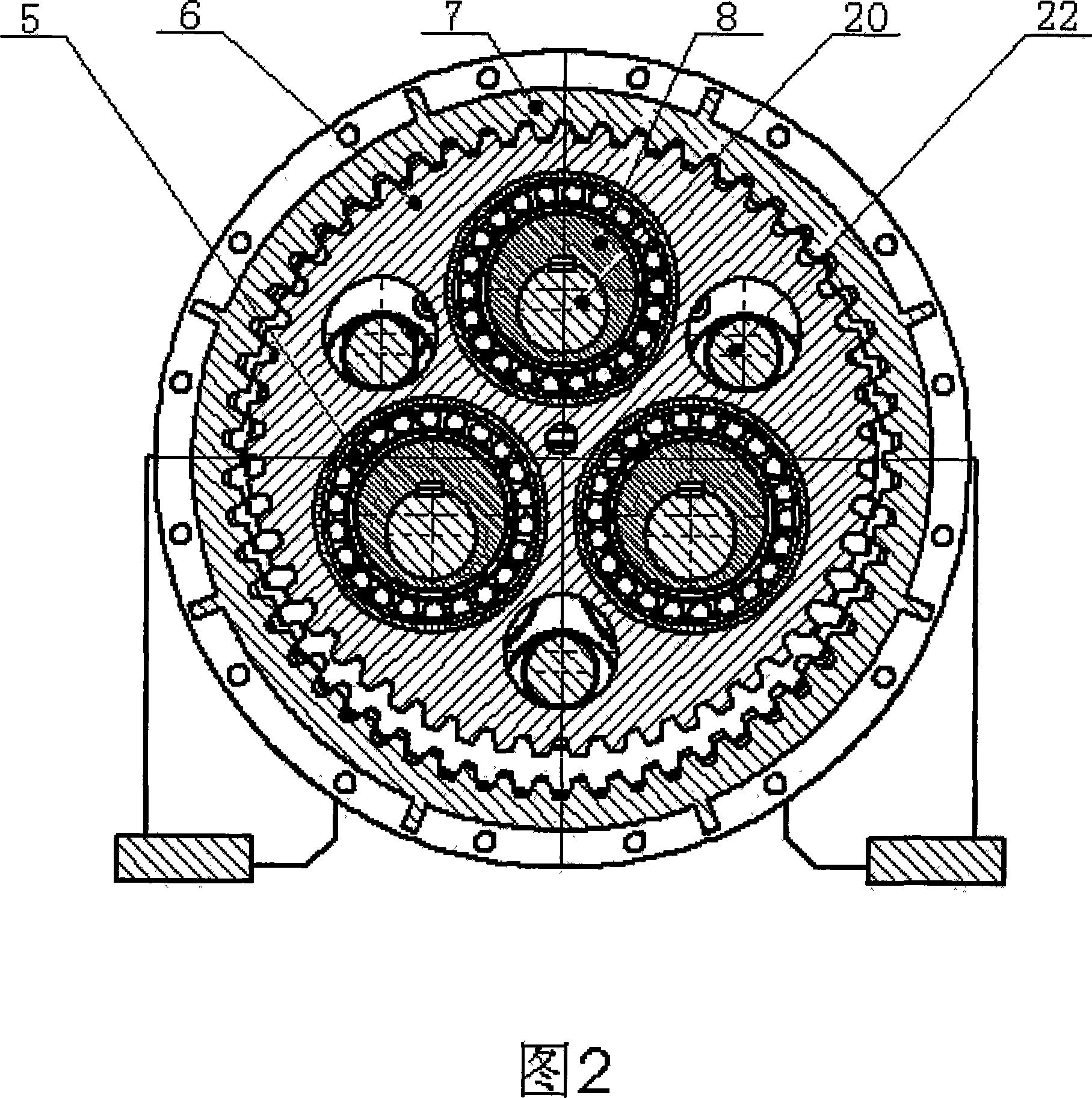
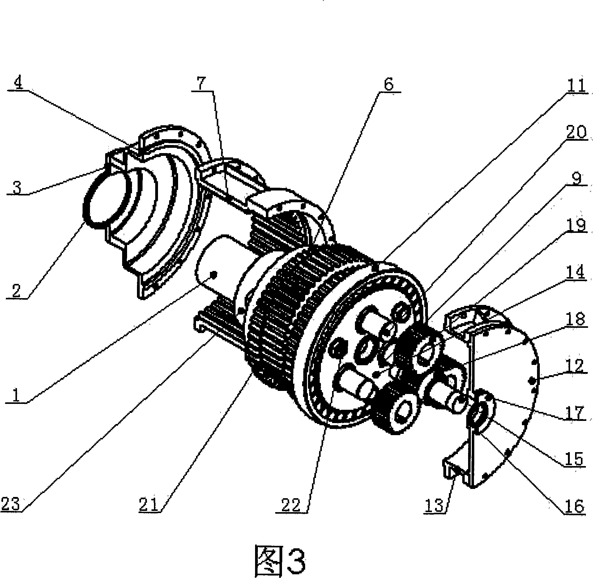
[0025] Referring to Fig. 1, Fig. 2 and Fig. 3, the present invention consists of an input gear shaft 15, a bearing frame 14, three synchronous planetary wheels 19, three triple key shafts 20, three connecting support rods 22, and two side gear ring plates 21 , an intermediate gear ring plate 6, an inner gear ring 7, an output shaft 1, and an eccentric sleeve 8, a side eccentric sleeve 10, a sealing ring 2, an output shaft end cover pressure plate 3, and an end cover 4.

[0026] One end of the output shaft 1 is equipped with a bearing 23 , the outer side of the bearing 23 is provided with an end cover 4 , the output shaft end cover pressing plate 3 is installed on the outside of the end cover 4 , and the sealing ring 2 is housed in the output shaft end cover pressing plate 3 . One end of input gear shaft 15 is equipped with bearin...


PUM


Abstract

The present invention discloses an internal three-ring decelerator, which consists of a bearing frame, an output axle, an input gear axle, two side tooth ring plates, a middle tooth ring plate, an internal tooth ring, and three eccentric crank axles, etc., wherein three eccentric crank axles are mutually paralleled; synchronous planet gears are respectively arranged on three eccentric crank axles, and arranged in a triangle, the small teeth number difference transmission is realized in the meshing process of two side tooth ring plates and the middle tooth ring plate with the internal tooth ring, the phase difference is 180 degrees finally, the qualities of two side tooth ring plates are respectively arranged into one seconds of the quality of the middle tooth ring plate; the bearing frame and the output axle are connected as a rigid frame structure, the circular disks at two end of the frame support three eccentric crank axles, the positions of the input gear axle and the output axle are positioned in an identical axial line, and the input gear axle is meshed with three synchronous planet gears. The present invention has the advantages that the reliability is high, the transmission ratio is large, the movement is steady, the carrying capacity is strong, and the layout is reasonable, thus being particularly suitable for being used under the working condition that the large power and the large torque are required.

Description

technical field [0001] The invention relates to the technical field of mechanical transmission, in particular to the technical field of reducers. Background technique [0002] In the modern industrial field, reducer equipment has been widely used. The three-ring reducer in the prior art has the characteristics of strong bearing capacity, large anti-overload capacity, high reliability in continuous production, large transmission ratio, high efficiency, long service life, convenient maintenance, and high cost performance, and is widely used in metallurgy, mining, A series of products have been formed for lifting transportation, construction, petrochemical, textile printing and dyeing and other industries. [0003] In many fields, the three-ring reducer replaces the hard tooth surface planetary reducer, cycloidal pin gear reducer, cylindrical gear reducer and worm gear reducer. The three-ring reducer in the prior art consists of three identical inner toothed ring plates arran...

Claims


Application Information

Patent Timeline
Patent Type & Authority Applications(China)
IPC IPC(8): F16H1/32
Inventor 冯凡谢雯彭新尧
Owner 北京瑞德信通用机械设备制造有限公司
Learn More