Built-in permanent magnet rotor structure of axial flux motor

A technology of axial magnetic flux and permanent magnet rotor, applied in the direction of magnetic circuit shape/style/structure, electromechanical devices, magnetic circuit rotating parts, etc., can solve problems such as insignificant salient pole effect and weak magnetic gathering ability of motors

Pending Publication Date: 2021-09-10
NANJING UNIV OF SCI & TECH
View PDF0 Cites 5 Cited by
  • Summary
  • Abstract
  • Description
  • Claims
  • Application Information

AI Technical Summary

Problems solved by technology

However, the current traditional axial field permanent magnet motor has a built-in structure of a single-layer magnetic accumulation rotor, the motor magnetic accumulation ability is not strong, and the salient pole effect is not obvious

Method used


Image

  • Built-in permanent magnet rotor structure of axial flux motor
  • Built-in permanent magnet rotor structure of axial flux motor
  • Built-in permanent magnet rotor structure of axial flux motor

Examples


Embodiment Construction

[0033] The following will clearly and completely describe the technical solutions in the embodiments of the present invention with reference to the accompanying drawings in the embodiments of the present invention. Obviously, the described embodiments are only some, not all, embodiments of the present invention. Based on the embodiments of the present invention, all other embodiments obtained by persons of ordinary skill in the art without making creative efforts belong to the protection scope of the present invention.

[0034] The purpose of the present invention is to provide a built-in permanent magnet rotor structure for an axial flux motor to solve the above-mentioned problems in the prior art, so that the motor has a stronger magnetic gathering ability, a salient pole effect, and a larger reluctance torque.

[0035] In order to make the above objects, features and advantages of the present invention more comprehensible, the present invention will be further described in d...


PUM


Abstract

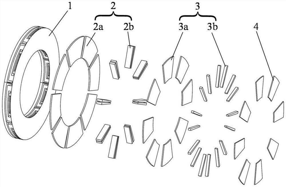
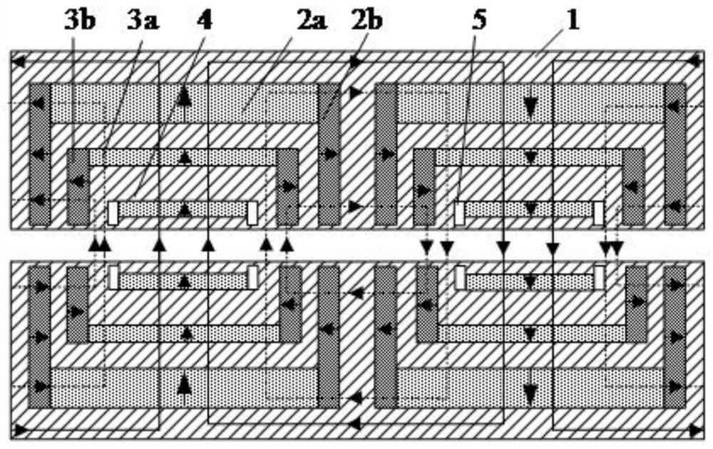
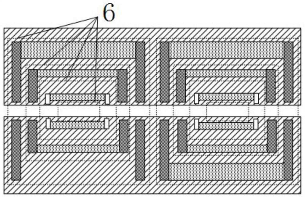
The invention discloses a built-in permanent magnet rotor structure of an axial flux motor. The built-in permanent magnet rotor structure comprises two rotor discs; each rotor disc comprises a rotor core with an annular cross section; each rotor core is formed by circumferentially winding a thin silicon steel sheet, and three layers of permanent magnet groups are uniformly embedded in the circumferential direction of each rotor core; each permanent magnet group comprises a first layer of U-shaped magnetism gathering structure permanent magnet combination, a second layer of U-shaped magnetism gathering structure permanent magnet combination and a third layer of linear structure permanent magnet which are sequentially arranged from the outer side of the rotor core to the circle center of the rotor core; the two rotor discs are installed on a rotating shaft in a manner that permanent magnet faces are opposite to each other, and a stator disc is arranged between the two rotor discs. According to the built-in permanent magnet rotor structure of the axial flux motor of the invention, the magnetism gathering capability of the permanent magnet rotor discs is stronger, and highly sinusoidal air gap flux density can be realized; the U-shaped permanent magnetcombinations and the linear permanent magnet combinations adopted, so that the salient pole effect of the motor can be improved, the reluctance torque is fully utilized, and the torque or power density of the motor is improved; and the silicon steel sheet is slotted and wound to form the rotor core, so that the machining is convenient and the structural strength is high.

Description

technical field [0001] The invention relates to the related technical field of permanent magnet motor rotors, in particular to a built-in permanent magnet rotor structure of an axial flux motor. Background technique [0002] Permanent magnet motors have the characteristics of high power density, high efficiency, and high reliability, and have been widely used in industrial production and household life. At present, in the cost of permanent magnet motors, permanent magnet materials occupy a large proportion, which causes the competitiveness of permanent magnet motors in low-end applications to decline. In order to improve the utilization rate of permanent magnets and the price competitiveness of permanent magnet motors, optimizing the structure of permanent magnet motors to improve their power and torque density has become an important research topic for experts and scholars at home and abroad. [0003] The interior permanent magnet motor is a permanent magnet motor structur...

Claims


Application Information

Patent Timeline
Patent Type & Authority Applications(China)
IPC IPC(8): H02K1/27H02K16/02
CPCH02K1/2793H02K16/02
Inventor 耿伟伟王晶侯继宁朱婷李强
Owner NANJING UNIV OF SCI & TECH
Why Eureka
Try Eureka