An axial magnetic field permanent magnet motor combined magnetization type permanent magnet built-in rotor

A permanent magnet motor, axial magnetic field technology, applied in electromechanical devices, electric components, magnetic circuit rotating parts, etc., can solve the difficulty of increasing the processing and installation of permanent magnets, the serious eddy current loss on the surface of permanent magnets, and the installation of permanent magnets. , protection difficulties, etc., to achieve the effect of obvious salient pole effect, high rotor structure strength, and good magnetic concentration effect

Active Publication Date: 2021-11-23
NANJING UNIV OF SCI & TECH
View PDF0 Cites 3 Cited by
  • Summary
  • Abstract
  • Description
  • Claims
  • Application Information

AI Technical Summary

Problems solved by technology

The main disadvantages of the surface-mounted structure are: the eddy current loss on the surface of the permanent magnet of the rotor is serious, the permanent magnet is difficult to fix, the structural strength of the rotor is not high, the reluctance torque cannot be used, and the magnetic density of the air gap is low, especially when the motor operates at high power and high speed. In the case of operation, the permanent magnet will also be subject to a large centrifugal force and the electromagnetic attraction of the stator, and the installation and protection of the permanent magnet has become a technical difficulty
[0003] The patent "An Axial Magnetic Field Permanent Magnet Ironless Motor with Magnetic Concentration Function" adopts the method of setting permanent magnetic strips to reduce magnetic flux leakage in the gap between two adjacent opposite-sex sectoral main magnetic poles of surface-mounted permanent magnets. The magnetic concentration effect is achieved. The patent "a hub motor based on the axial magnetic field of the rotor with a magnetic concentration structure" achieves the magnetic concentration effect by setting the first sector magnet and the second sector magnet whose magnetization directions are perpendicular to each other. However, these two methods The permanent magnet surface mount type can not avoid the disadvantages of the surface mount type structure
The patented "Stator Coreless Halbach Permanent Magnet Array Axial Flux Motor" uses Halbach permanent magnet array to achieve high air gap flux density, but the amount of permanent magnets is large, and the magnetization direction of each permanent magnet under each pole is different , which increases the difficulty of processing and installation of permanent magnets, and still uses a surface-mounted structure
[0004] To sum up, almost all the rotor structures of the axial field permanent magnet motors that can achieve the magnetic concentration effect at present adopt the permanent magnet surface-mounted structure. It is difficult to avoid the defects of the permanent magnet surface-mounted rotor structure, and there are still permanent magnets. Large eddy current loss, difficult installation and protection of permanent magnets, low structural strength, inability to utilize reluctance torque, low air gap flux density, high cost, etc.

Method used


Image

  • An axial magnetic field permanent magnet motor combined magnetization type permanent magnet built-in rotor
  • An axial magnetic field permanent magnet motor combined magnetization type permanent magnet built-in rotor
  • An axial magnetic field permanent magnet motor combined magnetization type permanent magnet built-in rotor

Examples


Embodiment

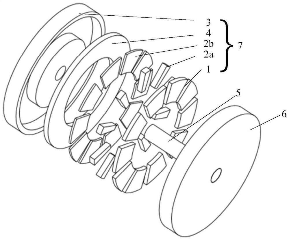
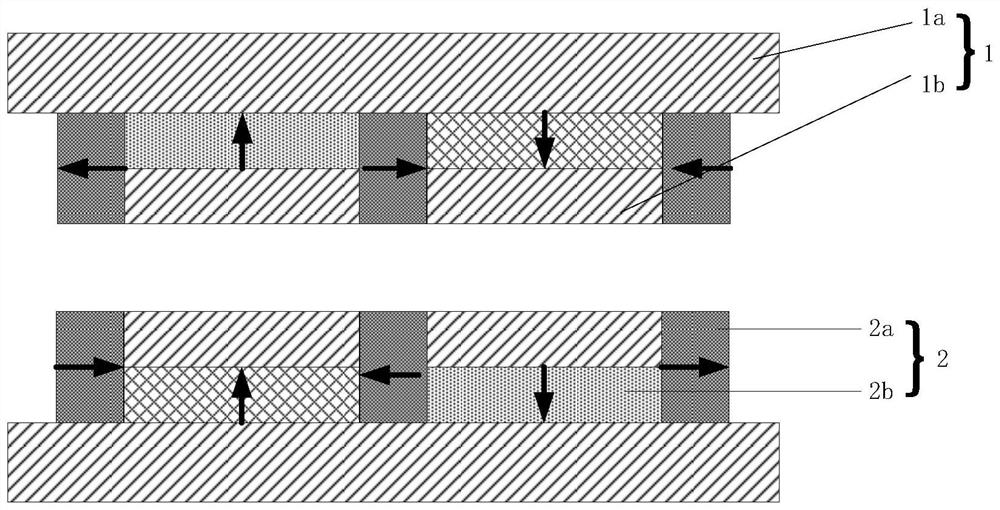
[0038] The present invention provides an axial field permanent magnet motor combined magnetization type permanent magnet built-in rotor structure, which has two permanent magnet rotor disks, and the two rotors are installed on the rotating shaft 5 in such a way that the permanent magnets face each other. The rotor structure mainly includes: rotor outer core 1a and rotor inner core 1b, permanent magnet 2a and permanent magnet 2b, rotor supporting shell 3, rotor back yoke 4, rotating shaft 5, first rotor disc 6, second rotor disc 7.

[0039] The rotor back yoke 4 is installed on the rotor support shell 3, and the bonding strength is enhanced by structural glue. The rotor support shell 3 can enhance the structural strength of the rotor, and is used to protect the iron core 1 and the permanent magnet 2, and reduce the speed of the rotor running at high speed. When the centrifugal force affects the rotor structure, the permanent magnets 2 are alternately and evenly arranged on the rot...


PUM


Abstract

The invention discloses a combined magnetization type permanent magnet built-in rotor of an axial magnetic field permanent magnet motor. The structure includes two rotor disks installed on a rotating shaft, and the first rotor disk includes a rotor core, a permanent magnet, and a rotor supporting shell. , The rotor back yoke, the permanent magnets include the first and second permanent magnets, the rotor core includes the rotor outer iron core and the rotor inner iron core; the rotor back yoke is installed on the rotor supporting shell, and the first and second permanent magnets alternate uniformly in the circumferential direction Arranged on the rotor back yoke; fix the rotor core with the second permanent magnet arranged on the rotor back yoke, so as to keep the permanent magnet fixed in the radial direction and axial direction; the rotor core, permanent magnet, rotor supporting shell The body and the rotor back yoke are fixed together to form the first rotor disk and installed on the rotating shaft, and then connected to the second rotor disk through the rotating shaft to fix the position of the second rotor disk in the axial direction to form a double rotor structure. The permanent magnet rotor of the invention has good magnetism gathering effect, high air gap flux density and large reluctance torque.

Description

technical field [0001] The invention relates to the technical field of axial flux permanent magnet motors, in particular to an axial magnetic flux permanent magnet motor combined magnetization type permanent magnet built-in rotor. Background technique [0002] Axial field PM motors, also known as disc PM motors, are an attractive alternative to cylindrical radial flux PM motors due to their pancake shape, compact construction, and high power density. Built-in type and surface-mounted type are two main rotor magnetic circuit structures, and in the axial field permanent magnet motor, the permanent magnet surface-mounted type structure is generally used. The main disadvantages of the surface-mounted structure are: the eddy current loss on the surface of the permanent magnet of the rotor is serious, the permanent magnet is difficult to fix, the structural strength of the rotor is not high, the reluctance torque cannot be used, and the magnetic density of the air gap is low, espe...

Claims


Application Information

Patent Timeline
Patent Type & Authority Patents(China)
IPC IPC(8): H02K1/27H02K1/28H02K16/02
CPCH02K1/2793H02K1/28H02K16/02
Inventor 耿伟伟侯继宁朱婷
Owner NANJING UNIV OF SCI & TECH
Why Eureka
Try Eureka