
Float type liquid level gauge with vernier display

A float type and liquid level gauge technology, which is applied in the direction of buoy liquid level indicators, etc., can solve the problems of unusable, increased float weight, and increased float volume, so as to reduce the cost of use and maintenance, and overcome the difficulty of reading values , to ensure the effect of measurement accuracy

Active Publication Date: 2018-10-23
DALIAN JIAXIN ELECTROMECHANICAL INSTR CO TD
View PDF12 Cites 1 Cited by
  • Summary
  • Abstract
  • Description
  • Claims
  • Application Information

AI Technical Summary

Problems solved by technology

But it has the following disadvantages: both the float and the vernier are sliding friction, resulting in a large friction coefficient, which makes the friction force large and affects the accuracy and sensitivity of the measurement, and is even unusable.
Its disadvantages are: 1. The float is a sliding friction, which leads to a large friction coefficient and friction force, which affects the accuracy and sensitivity of the measurement; 2. The arrangement of magnetic steel in the entire circle of the float increases the weight of the float, which will inevitably increase the weight of the float. 3. The demagnetization temperature of the magnetic steel limits the service temperature of the liquid level gauge
Moreover, the linear bearing itself is heavy, which will inevitably increase the weight of the cursor. The increase in the weight of the cursor requires a greater magnetic force to couple, which further increases the mechanical friction, and thus requires a greater buoyancy of the float, which brings more pressure. multiple related questions
2. The cost remains high: imported linear bearings are about 50 yuan each, linear guides made of aluminum alloy are about 6-7 yuan per meter, and imported ones are about 100 yuan per meter. When the range is large, it accounts for a large proportion of the total cost. larger
3. The rigidity of the guide rail is poor. The rigidity of the cylindrical linear guide rail matched with the cylindrical linear bearing decreases with the increase of the length of the guide rail. When the cursor and the floating ball are under the action of the magnetic coupling force, the guide rail will bend toward the direction of the floating ball chamber. unavailable when large
If the rigidity of the guide rail is increased, the diameter of the guide rail needs to be increased, which will inevitably increase the weight of the linear bearing, which will not only further increase the mechanical friction force, but even cause the floating ball to sink into the liquid and become unusable due to the increase in weight
4. There are many joints on the guide rail, and the matching accuracy of the linear guide rail and the linear bearing is very high. The linear guide rail is made by mechanical precision machining. Due to the rigidity requirements of the guide rail during mechanical precision machining, each guide rail cannot be processed very long. When the range of liquid level measurement is large, it needs to be connected by multiple guide rails. The connection between the two ends of each guide rail and other guide rails must ensure accuracy. This is a difficult task, otherwise, the linear bearing will be stuck between the two guide rails. Junction
It is understood that when the imported magnetic floating ball is used in high temperature occasions, the service life is about 4 to 5 years, and the overhaul period of the equipment in the petrochemical industry is 3 years. Therefore, it is necessary to replace an imported magnetic floating ball in 3 years. It can be seen that the use of the liquid level gauge the cost is too high

Method used


Image

  • Float type liquid level gauge with vernier display
  • Float type liquid level gauge with vernier display
  • Float type liquid level gauge with vernier display

Examples


Embodiment 1

[0084] (1) Basic type

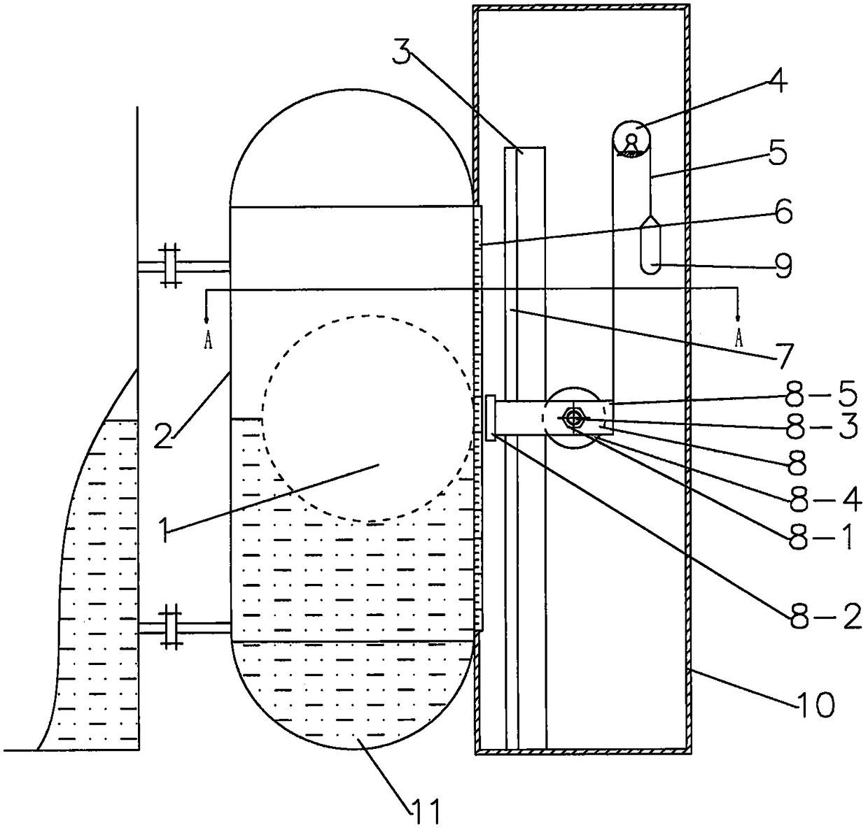
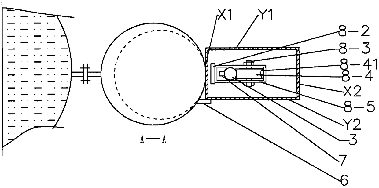
[0085] A float type liquid level gauge displayed by a vernier, such as figure 1 with figure 2 As shown, it includes a float chamber 2 made of non-ferromagnetic material, a spherical float 1 made of ferromagnetic material in the float chamber 2, a scale 6 adjacent to the float chamber 2, a cylindrical guide rail 3, and a closed non-ferrous The cursor chamber 10 of magnetic transparent material, the scale 6, the axis of the cylindrical guide rail 3 and the axis of the cursor chamber 10 are parallel to each other and parallel to the axis of the float chamber 2, and the vernier 8 and the cylindrical guide rail 3 are respectively arranged on Inside the cursor chamber 10;

[0086] The cylindrical guide rail 3 is provided with a guide rail reinforcing rib plate 7 from top to bottom on the side close to the float chamber 2;

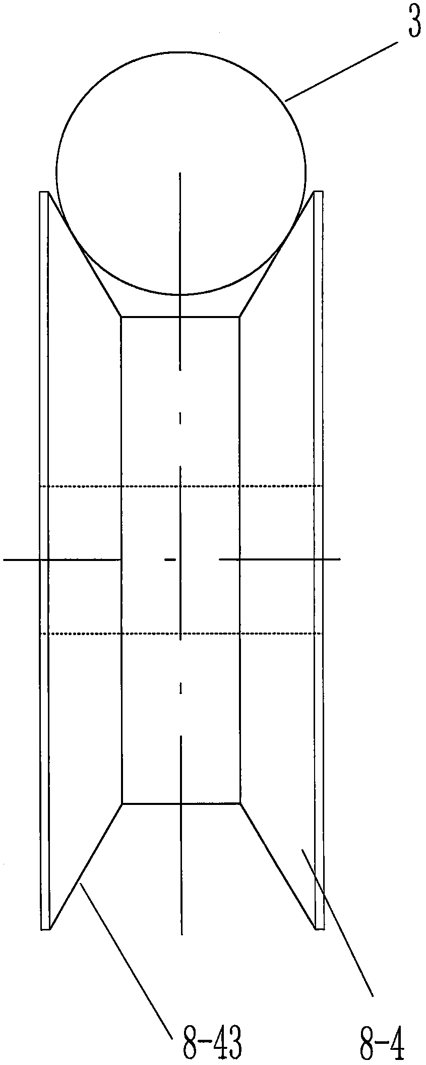
[0087] Wherein, described vernier 8 comprises magnetic steel 8-2, rectangular frame 8-5 and rolling system, and described rolling sys...

Embodiment 2

[0101] Another float type liquid level gauge displayed by the vernier, such as Figure 4 with Figure 5 As shown, it is different from the protective type of embodiment 1 in that the vernier guide rail is a rectangular parallelepiped guide rail 3'; correspondingly, the radial groove of the scroll wheel 8-4 is a rectangular groove 8-42 , the distance between the two inner parallel surfaces of the rectangular groove 8-42 is greater than the distance between the two outer surfaces corresponding to the guide rail 3'. Under the action of magnetic coupling between the magnetic steel 8-2 on the vernier 8 and the floating ball 1, the rolling wheel 8-4 rolls along the working surface of the cuboid guide rail 3'.

[0102] Further, in order to avoid the trouble of replacing the magnetic steel 8-2 after the magnetic steel 8-2 is demagnetized, the liquid level gauge is provided with a spare vernier 14 at the upper position in the vernier chamber 10, and correspondingly outside the vernier...

Embodiment 3

[0104] Another float-type liquid level gauge with a vernier display, on the basis of the aforementioned liquid level gauge, has improved its vernier 8, that is, the vernier 8 includes two sets of the rolling system, that is, includes two scroll wheels 8 -4, 8-4' and their respective shafts 8-3, 8-3' and rolling bearings 8-1, 8-1', such as Image 6 shown. The two sets of rolling systems are arranged in parallel up and down in the same rectangular frame 8-5, and the plane formed by the two shafts 8-3, 8-3' is perpendicular to the ground, so as to prevent the cursor 8 from The rotation around the axis is generated during the up and down movement, which improves the accuracy and reliability of use.


PUM


Abstract

The invention relates to a ball float type liquidometer with vernier display. The ball float type liquidometer comprises a ball float chamber and a ferromagnetic spherical floating ball arranged therein, a vernier outside the ball float chamber, a calibrated scale and a vernier guide rail. The vernier comprises magnetic steel, a frame and a rolling system which is horizontally fixed and sleeved in the frame; the rolling system comprises rolling wheels which are provided with radial grooves along a circumferential surface, rolling bearings and shafts; the magnetic steel is disposed between the ball float chamber and the frame and is fixed outside one side surface close to the ball float chamber on the frame, and the magnetic pole of the magnetic steel is right oriented towards the floating ball; the vernier guide rail is sleeved in the frame and is disposed between the magnetic steel and the rolling system; and the rolling system enables the rolling wheels to roll vertically along the vernier guide rail at groove positions through a magnetic coupling force between the magnetic steel and the floating ball. The ball float type liquidometer is simple and scientific in structure, reliable in application performance, easy to manufacture and low in cost, reduces defects in the prior art and effectively meets needs in correlation fields.

Description

technical field [0001] The invention relates to liquid level measuring equipment, in particular to a float type liquid level gauge displayed by a vernier. Background technique [0002] Existing on-the-spot indicating liquid level instruments include glass plate type, magnetic flap (column) type, buoy type, two-color water level gauge, etc. The glass plate type can only be visually inspected at close range, and it is difficult to visually inspect after being covered with dust or contaminated by media, and the pressure resistance is limited. The structure of the magnetic flap (column) is relatively complicated and prone to garbled characters. In addition, the magnetic steel in the floating ball also has the problem of high temperature demagnetization, which affects its long-term use. After 4 to 5 years, the floating ball has to be replaced due to the demagnetization of the magnetic steel in the floating ball. The applicable medium range of the two-color water level gauge is ...

Claims


Application Information

Patent Timeline
Patent Type & Authority Patents(China)
IPC IPC(8): G01F23/30
Inventor 王嘉贤梁有祥王晓日张烁高臻强
Owner DALIAN JIAXIN ELECTROMECHANICAL INSTR CO TD
Learn More