Built-in permanent magnet rotor disc and disc type motor

A technology for permanent magnet rotors and disc motors, which is applied to rotating parts of magnetic circuits, synchronous motors with stationary armatures and rotating magnets, magnetic circuits, etc. Instability and other problems, to achieve the effect of obvious salient pole effect, less permanent magnet consumption and good stability

Pending Publication Date: 2022-03-15
NANJING UNIV OF SCI & TECH
View PDF4 Cites 3 Cited by
  • Summary
  • Abstract
  • Description
  • Claims
  • Application Information

AI Technical Summary

Problems solved by technology

The commonly used axial permanent magnet motor rotor is a surface-mounted structure. The surface-mounted structure is simple in structure, easy to install, small in size and light in weight, but it is difficult to fix the permanent magnet. During the rotation of the rotor, the surface-mounted structure The permanent magnet will be affected by centrifugal force and magnetic pulling force, which will cause the rotor structure to be unstable during long-term work, and the surface-mounted rotor has almost the same inductance of the orthogonal and direct axes, resulting in a small reluctance torque and poor magnetic field weakening capability. When the rated torque is fixed, the reluctance torque is small, and the permanent magnet torque is required to be large, which requires a large amount of permanent magnets

Method used


Image

  • Built-in permanent magnet rotor disc and disc type motor
  • Built-in permanent magnet rotor disc and disc type motor
  • Built-in permanent magnet rotor disc and disc type motor

Examples


Embodiment 1

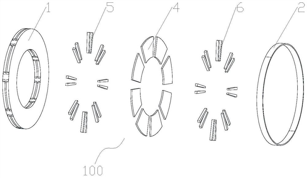
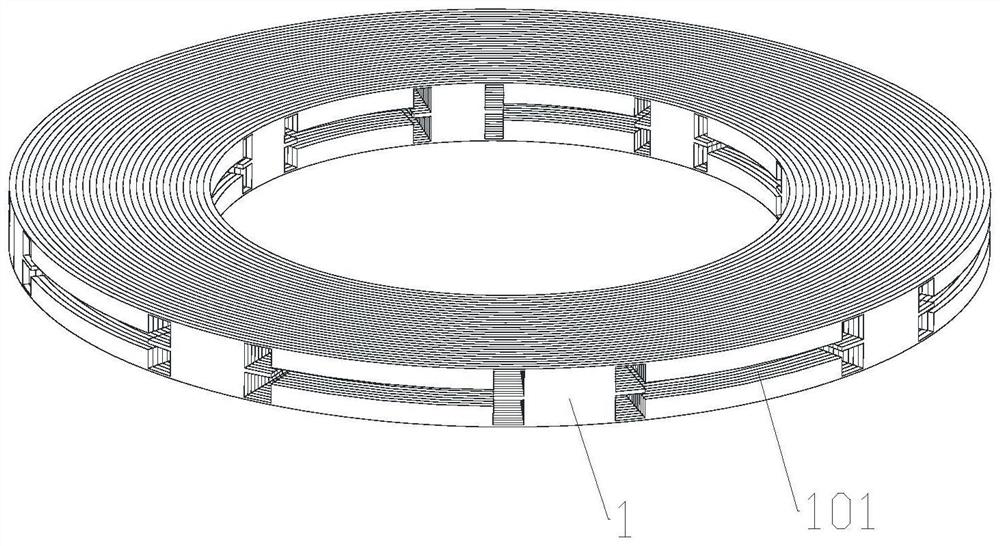
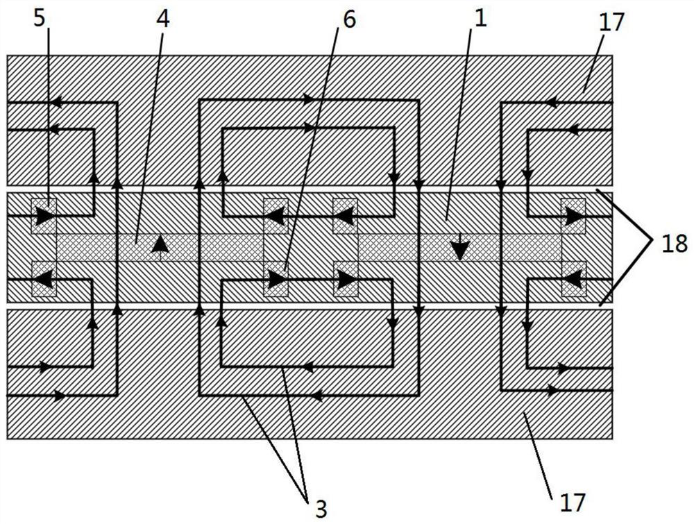
[0032] refer to Figure 1-Figure 8 As shown, the built-in permanent magnet rotor disk 100 provided by this embodiment includes: an annular rotor core 1, a non-magnetic protective cover 2 and a plurality of first permanent magnet groups, and the plurality of first permanent magnet groups are arranged along the annular rotor core. The circumferential direction of 1 is evenly arranged, and there is a gap between any two adjacent first permanent magnet groups, each first permanent magnet group is embedded in the inner of the annular rotor core 1, and the annular rotor core 1 is sleeved on the motor. On the non-magnetic support 12, the non-magnetic protective cover 2 is arranged on the outer wall of the annular rotor core 1, and the non-magnetic protective cover 2 restricts the radial direction of the first permanent magnet group when the annular rotor core 1 rotates. The direction of magnetization of any two adjacent first permanent magnet groups is opposite, and the first permane...

Embodiment 2

[0043] refer to Figure 4 As shown, this embodiment includes some or all of the features of Embodiment 1. The difference is that any two adjacent first permanent magnet groups of the built-in permanent magnet rotor disk 100 provided in this embodiment share a first Tangential permanent magnet 5 and a second tangential permanent magnet 6.

Embodiment 3

[0045] refer to Figure 5 As shown, this embodiment includes some or all of the features of Embodiment 1. The difference is that the first permanent magnet group of the built-in permanent magnet rotor disk 100 provided by this embodiment includes a symmetrically arranged first U-shaped permanent magnet and a second permanent magnet. Two U-shaped permanent magnets, the first U-shaped permanent magnet includes a second axial permanent magnet 7 and two third tangential permanent magnets 8 symmetrically arranged on both sides of the second axial permanent magnet 7, the second U-shaped permanent magnet It includes a third axial permanent magnet 9 and two fourth tangential permanent magnets 10 symmetrically arranged on both sides of the third axial permanent magnet 9 .

[0046] Further, as Figure 5 As shown, in this embodiment, the magnetization directions of the second axial permanent magnet 7 and the third axial permanent magnet 9 are the same in the axial direction; the magneti...


PUM


Abstract

The invention discloses a built-in permanent magnet rotor disc and a disc type motor comprising the built-in permanent magnet rotor disc, and relates to the field of permanent magnet motor rotors, the rotor disc comprises an annular rotor iron core, a non-magnetic conductive protective sleeve and a plurality of first permanent magnet groups, the plurality of first permanent magnet groups are uniformly arranged along the circumferential direction of the annular rotor iron core, a gap is formed between any two adjacent first permanent magnet groups, each first permanent magnet group is embedded in the annular rotor iron core, the annular rotor iron core is sleeved on a non-magnetic support of the motor, the non-magnetic protective sleeve is arranged on the outer side wall of the annular rotor iron core, and any two adjacent first permanent magnet groups are opposite in magnetizing direction. The first permanent magnet group, the annular rotor core and a stator disc of the motor can form a first closed magnetic circuit. The rotor disc permanent magnets are embedded, so that the stability of the rotor is good, the built-in structure enhances the magnetism gathering capability of the rotor, improves the salient pole effect of the rotor, improves the reluctance torque, and reduces the permanent magnet consumption of the rotor under the same power level.

Description

technical field [0001] The invention relates to the field of permanent magnet motor rotors, in particular to a built-in permanent magnet rotor disc and a disc motor thereof. Background technique [0002] Axial flux permanent magnet machine (AFPMM) is also called disc permanent magnet motor. The air gap of the axial permanent magnet motor is planar, and the air gap magnetic field is distributed along the axial direction. In recent years, axial motors have attracted more and more attention from researchers at home and abroad due to their advantages such as compact structure, high efficiency, and high power density. The occasions requiring high torque density and compact space have also been more and more widely used. The commonly used axial permanent magnet motor rotor is a surface-mounted structure. The surface-mounted structure is simple in structure, easy to install, small in size and light in weight, but it is difficult to fix the permanent magnet. During the rotation of...

Claims


Application Information

Patent Timeline
Patent Type & Authority Applications(China)
IPC IPC(8): H02K1/27H02K1/2713H02K21/14H02K1/28
CPCH02K1/27H02K1/2713H02K21/14H02K1/28
Inventor 耿伟伟葛士荣王晶张雨晴
Owner NANJING UNIV OF SCI & TECH
Why Eureka
Try Eureka