Stator assembly method and laminated stator manufactured by same

An assembly method and lamination technology, applied in the manufacture of stator/rotor body, magnetic circuit shape/style/structure, magnetic circuit static parts, etc., can solve the problems of low slot full rate and many winding heads, etc. Increase the space, reduce the eccentricity, and overcome the effect of many winding connections

Active Publication Date: 2010-05-19
NIDEC MOTOR (QINGDAO) CORPORATION
View PDF5 Cites 8 Cited by
  • Summary
  • Abstract
  • Description
  • Claims
  • Application Information

AI Technical Summary

Problems solved by technology

The stator structure has problems such as

Method used


Image

  • Stator assembly method and laminated stator manufactured by same
  • Stator assembly method and laminated stator manufactured by same
  • Stator assembly method and laminated stator manufactured by same

Examples


Embodiment Construction

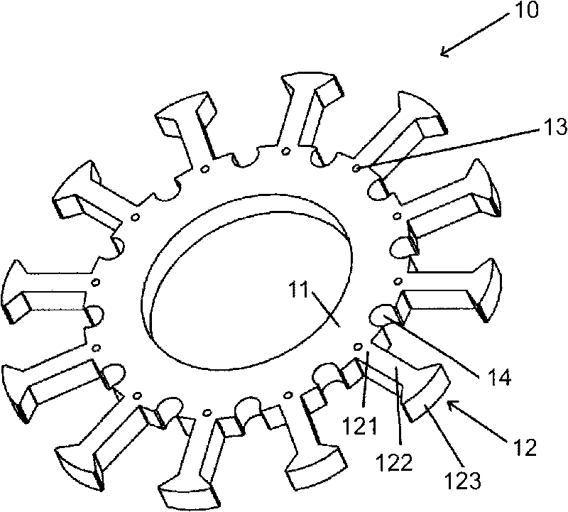
[0036] figure 1 Shown is a thinner lamination 10 than a conventional stator lamination. The sheet 10 has a ring portion 11 and tooth pieces 12 arranged at equal angular intervals along the outer circumference of the ring portion. The tooth piece 12 is T-shaped as a whole, and has a tooth root portion 121 , a tooth body portion 122 and a tooth end portion 123 along the radial direction. The tooth end portion 123 has an arc surface in the circumferential direction. The configuration of the tooth piece 12 can prevent the winding wire from slipping off from the tooth. The tooth tip portions of all the teeth of the entire foil 10 define an imaginary peripheral surface. Preferably, the gear piece 12 is integrated with the ring portion 11 . As an example, the foil 10 is shown with 12 teeth. A positioning hole 13 is provided at the tooth root of each gear piece 12 . Optionally, a notch 14 is provided at the central part of the ring portion 11 between two adjacent teeth (ie, the...


PUM


Abstract

The invention provides an assembly method of a laminated stator for a motor, which comprises the steps of: a, providing a plurality of laminated plates, wherein each laminated plate comprises a ring part with a center line and a plurality of teeth arranged at intervals of equal angle distances along the circumferential direction of the ring part, and the teeth of all laminated plates are equal; b, sequentially coaxially fixing the laminated plates to enable the laminated plates to be arranged at a distance of preset axial distance mutually; and c, rotating the laminated plates around the common center line to a preset angle position, pressing the laminated plates to enable the ring parts of the laminated plates to be overlapped on the axial direction, wherein the teeth of the laminated plates are crossly arranged along the circumferential directions of the ring parts, and thereby a tooth of another laminated plate is arranged between every two adjacent teeth of each laminated plate. The invention also provides a laminated stator manufactured by the assembly method.

Description

technical field [0001] The present invention generally relates to a method for assembling a stator, and more particularly, relates to a method for assembling a laminated stator for an electric motor and a stator manufactured by the method. Background technique [0002] see Figure 10 As shown, in the traditional integral stator core structure for brushless permanent magnet motors, the stator core forms a round hole in the center, and forms a plurality of radial slots on the outer peripheral surface, and coils are wound inside the slots , stator teeth are formed between the two wire slots, the free ends of the stator teeth are arc surfaces with a certain radian, and the end arc surfaces of all the stator teeth define an annular peripheral surface concentric with the circular hole, and the wire slots are There is a slit on the peripheral surface where the free ends of the stator teeth are located, through which the winding pins for guiding the coil wires pass through during wi...

Claims


Application Information

Patent Timeline
IPC IPC(8): H02K15/02H02K1/14
Inventor 王瑞梅李先发孙亮高祀法
Owner NIDEC MOTOR (QINGDAO) CORPORATION
Why Eureka
Try Eureka