Finger print input module

A fingerprint input and module technology, applied in character and pattern recognition, instruments, computer components, etc., can solve problems such as reducing mass production yield

Inactive Publication Date: 2009-04-29
巫仁杰
View PDF1 Cites 16 Cited by
  • Summary
  • Abstract
  • Description
  • Claims
  • Application Information

AI Technical Summary

Problems solved by technology

[0004] Although the fingerprint input module 1 can produce bright and dark fingerprint images, in order to make the light emitted by the light emitting unit 11 refract into the microprism strip 121 at a correct angle, so that the large area of ​​the placement surface 122 Part of the area can meet the requirement of a total reflection angle, and the installation angle of the light-emitting unit 11 must have a strict assembly accuracy requirement; The angle of the imaging unit 13 enters into the imaging unit 13 to avoid the formation of undesigned imaging aberrations on the image sensing element 132. The installation angle of the imaging unit 13 must also have a strict assembly accuracy requirement; and the above two components 11 , 13 The assembly accuracy requirement on the installation angle makes it easy to produce defective products due to the angle error on the assembly during mass production, which reduces the yield rate of mass production

Method used


Image

  • Finger print input module
  • Finger print input module
  • Finger print input module

Examples


Embodiment Construction

[0015] The present invention is described in detail below in conjunction with accompanying drawing and four embodiments:

[0016] Before the present invention is described in detail, it should be noted that in the following descriptions, similar components are represented by the same numbers, and in order to make the technical features clear, the drawing ratio of the dimensions of each component will be compared with the actual different.

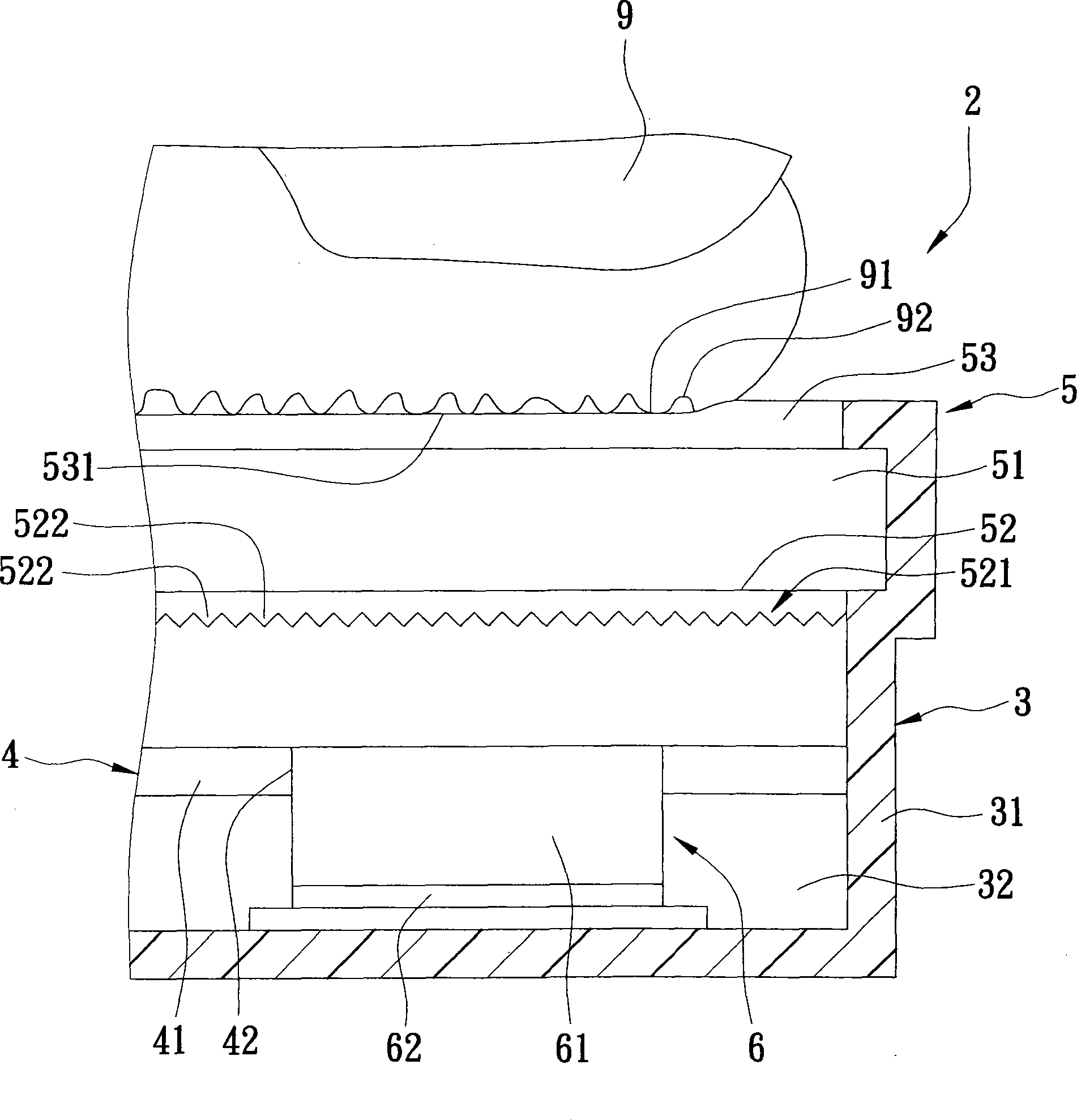
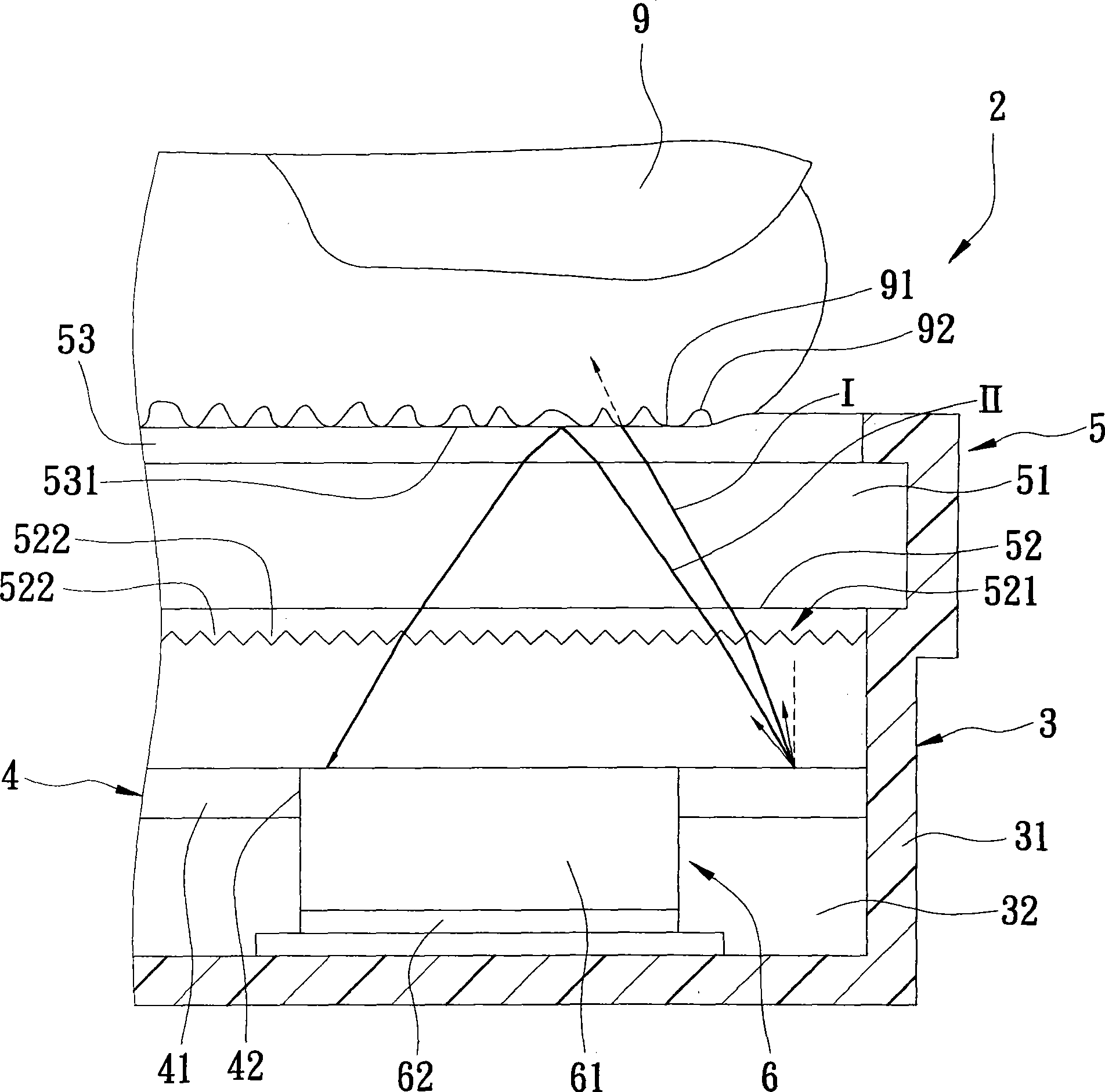
[0017] refer to figure 2 , illustrating a first preferred embodiment of the fingerprint input module 2 of the present invention, which can be used to input a fingerprint formed by a combination of a plurality of crest areas 91 and trough areas 92 in a finger 9 to be captured, such as the thumb, index finger, etc. ; And the fingerprint input module 2 includes a housing 3 , a light emitting unit 4 , an imaging unit 5 , and an imaging unit 6 .

[0018] The casing 3 includes a casing wall 32 forming an accommodating space 31 .

[0019] The ...


PUM


Abstract

The invention discloses a fingerprint input module group which comprises a light emitting unit, an imaging unit and an image sampling unit. The light emitting unit comprises a plane light source for emitting lights and a light harvesting punch hole. The imaging unit comprises a transparent substrate which is septal to the plane light source and at least one micro-prism element which is arranged on the substrate; the image sampling unit and the imaging unit are respectively arranged at the two opposite sides of the emitting unit. Lights are collected by the light harvesting punch hole and are converted into an image signal. By the septal between the plane light source and the substrate and due to the fact that the image sampling unit and the imaging unit are respectively arranged at the two opposite sides of the emitting unit, the image sampling unit can obtain clearly demarcated bright and dark fingerprint images. Therefore, the required installation precision of the units which are mutually overlapped can be lowered greatly, and the yield rate can be improved.

Description

technical field [0001] The invention relates to a component of a pattern recognition device, in particular to a fingerprint input module. Background technique [0002] For the activation of modern personal electronic equipment, or the reading of data after activation, a program to identify the user's identity is often designed, and the method of using fingerprints to identify the user's identity has the ability to truly identify the correct use of characteristics of the recipient. [0003] refer to figure 1 , is a fingerprint input module 1 disclosed in U.S. Patent No. 5,796,858. The fingerprint input module 1 includes a light-emitting unit 11 emitting light, a microprism unit 12, and an image-taking unit 13; wherein, The microprism unit 12 includes a plurality of microprism strips 121 extending along a direction, and a placement surface 122 for placing fingers to be imaged; A lens 131 for the light, and an image sensor 132 for converting the light into an image signal fo...

Claims


Application Information

Patent Timeline
Patent Type & Authority Applications(China)
IPC IPC(8): G06K9/00
Inventor 巫仁杰
Owner 巫仁杰
Why Eureka
Try Eureka