Light source device

A light source device, laser technology, applied in the direction of light source, point light source, light source combination, etc., can solve problems such as laser energy loss

Inactive Publication Date: 2011-03-30
SHARP KK
View PDF11 Cites 8 Cited by
  • Summary
  • Abstract
  • Description
  • Claims
  • Application Information

AI Technical Summary

Problems solved by technology

Laser energy is lost (Stokes loss) as the wavelength of the laser light is converted by the fluorescent substance that absorbs the laser light

Method used


Image

  • Light source device
  • Light source device
  • Light source device

Examples


no. 1 approach

[0058] (constitute)

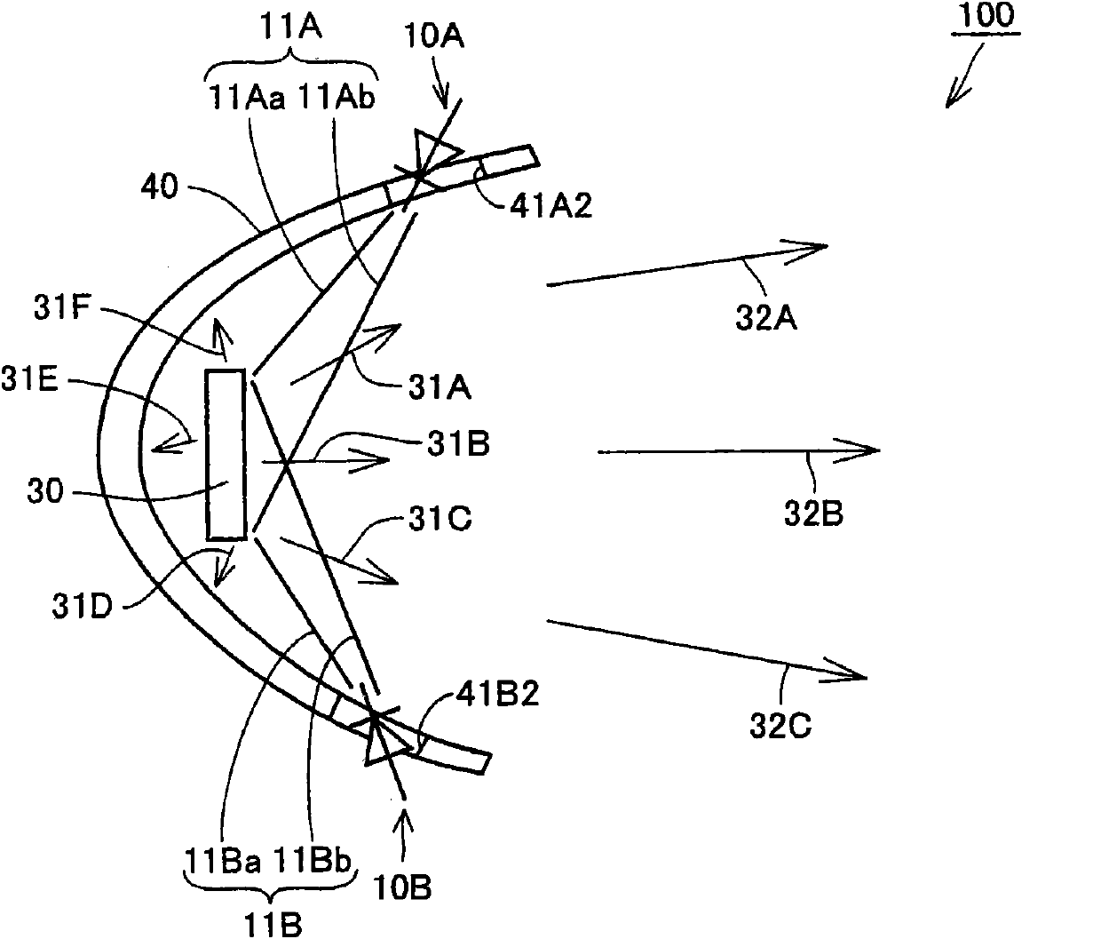
[0059] refer to figure 1 , the light source device 100 of this embodiment will be described. The light source device 100 includes a first semiconductor laser element 10A, a second semiconductor laser element 10B, a light scatterer 30 , and a substantially concave reflector 40 .

[0060] (semiconductor laser element)

[0061] The first semiconductor laser element 10A oscillates the first laser light 11A having a wavelength in the visible region. The second semiconductor laser element 10B oscillates the second laser light 11B having a wavelength in the visible region. Preferably, first semiconductor laser element 10A emits first laser beam 11A having a blue wavelength, and second semiconductor laser element 10B emits second laser beam 11B having a yellow wavelength different from first laser beam 11A. The combination of colors is not limited to blue and yellow. There are no particular limitations on the type or configuration of the laser light to be os...

no. 2 approach

[0093] (constitute)

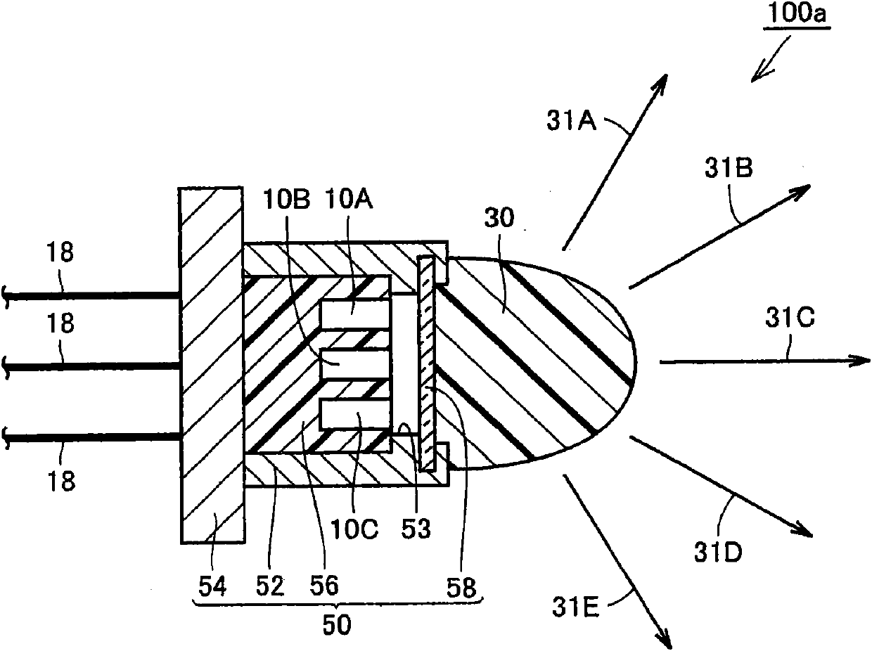
[0094] refer to figure 2 , the light source device 100a of this embodiment will be described. This light source device 100 a includes a first semiconductor laser element 10A, a second semiconductor laser element 10B, a third semiconductor laser element 10C, a light scatterer 30 , and a housing 50 .

[0095] Each of the semiconductor laser elements 10A, 10B, and 10C oscillates laser light having a wavelength in the visible region, as in the first embodiment. The laser beams oscillated from the semiconductor laser elements 10A, 10B, and 10C have different wavelengths.

[0096] The housing 50 is configured in a box shape from a metal cap portion 52 , a base portion 54 , a heat sink 56 , and glass 58 as a light-transmitting member having light transmission properties. The glass 58 is attached to the window portion 53 opened in the metal cap portion 52 . The respective semiconductor laser elements 10A, 10B, and 10C are mounted inside the case 50 .

[009...

no. 3 approach

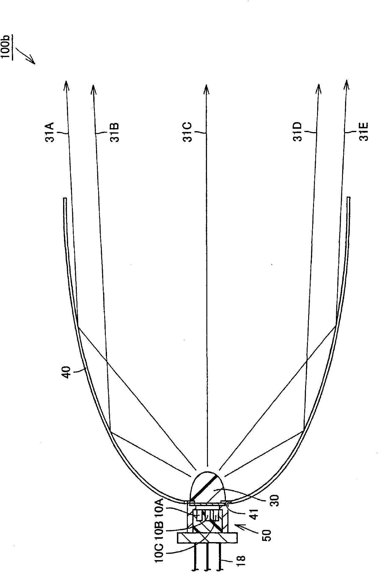
[0115] refer to image 3 , the light source device 100b of this embodiment will be described. Here, only differences from the light source device 100a of the second embodiment described above will be described. The light source device 100 b is the same as the light source device 100 of the first embodiment, and further includes a substantially concave reflector 40 .

[0116] Preferably mirror 40 has a focal point. Preferably light scatterer 30 is configured to contain the focal point of mirror 40 . The respective laser beams oscillated from the respective semiconductor laser elements 10A, 10B, and 10C are irradiated to the light-scattering body 30 through the opening 41 provided in the reflection mirror 40 .

[0117] (Effect)

[0118] The operation and effect of the light source device 100b of this embodiment will be described. The light source device 100 b emits the scattered light beams 31A to 31E without converting the wavelength of each laser beam by the light scatter...


PUM


Abstract

A light source device includes a first semiconductor laser element that oscillates a first laser beam having a visible-region wavelength, a second semiconductor laser element that oscillates a second laser beam having a visible-region wavelength, and a light-scattering body that is irradiated with first laser beam and second laser beam to scatter first laser beam and second laser beam without changing the wavelengths. Because the wavelengths are not converted, first laser beam and second laser beam oscillated from first semiconductor laser element and second semiconductor laser element are emitted without generating energy losses of first laser beam and second laser beam.

Description

technical field [0001] The present invention relates to a light source device using a semiconductor laser element as a light source. Background technique [0002] Instead of various light source devices such as incandescent lamps, fluorescent lamps, and discharge tubes, light source devices using laser light oscillated from a semiconductor laser element as a light source have been proposed. [0003] Japanese Patent Application Laid-Open No. 2008-43754 discloses a light emitting device including a semiconductor laser element (excitation light source), an optical fiber, and a wavelength conversion member. The wavelength conversion member has a fluorescent substance. The fluorescent substance absorbs laser light irradiated from the semiconductor laser element. The fluorescent substance that absorbs the laser light converts the wavelength of the laser light, and emits illumination light in an arbitrary wavelength region (color). [0004] Japanese Patent Application Laid-Open ...

Claims


Application Information

Patent Timeline
Patent Type & Authority Applications(China)
IPC IPC(8): H01S5/00
CPCG02B6/0008F21K9/00F21K9/52H01S5/005F21Y2101/025F21Y2101/02H01S5/02292F21Y2113/02H01S5/4012H01S5/02284F21Y2101/00F21K9/61F21Y2113/20F21Y2115/30H01S5/02212H01S5/0087H01S5/0225H01S5/02251H01S5/02255
Inventor 高桥幸司
Owner SHARP KK
Why Eureka
Try Eureka