Main cable splay saddle for self-anchorage suspension bridge

A technology of self-anchored suspension bridges and loose cable saddles, applied in bridges, bridge parts, bridge construction, etc., can solve the problems of small-scale main cables, difficult to locate accurately, low economic benefits, etc. Vertical size, high economic benefit effect

Active Publication Date: 2015-11-18
SHANGHAI MUNICIPAL ENG DESIGN INST GRP
View PDF6 Cites 5 Cited by
  • Summary
  • Abstract
  • Description
  • Claims
  • Application Information

AI Technical Summary

Problems solved by technology

However, the vertical component force generated by the main cable due to the corner will act on the stiffening beam at the base of the scatter saddle, causing additional bending moment to it, which is not good for the stiffening beam; after the main cable turns, the stiffening beam is required to provide a larger anchorage surface, which needs to be added High girder, poor economic benefit
If the loose cable sleeve structure is adopted, the center of the main cable remains unchanged, and the radial size and shape of the main cable are constrained only by the loose cable sleeve, which has no effect on the stress on the stiffening beam; but when the main cable strands are scattered, the cable force supports the top loose cable sleeve upward. Sliding, it is necessary to set the clamping section to provide clamping force and anti-sliding friction resistance; the main cable strands do not have groo

Method used


Image

  • Main cable splay saddle for self-anchorage suspension bridge
  • Main cable splay saddle for self-anchorage suspension bridge
  • Main cable splay saddle for self-anchorage suspension bridge

Examples


Embodiment Construction

[0026] based on the following Figure 1 to Figure 9 , specifically explain the preferred embodiment of the present invention.

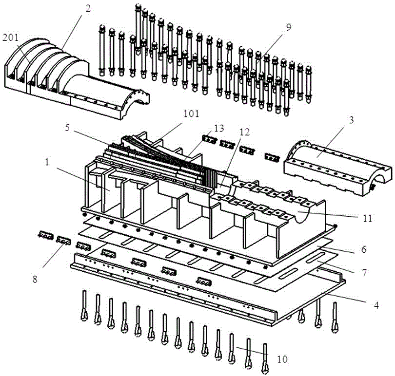
[0027] Such as Figure 1 to Figure 7 As shown, the present invention provides a main cable scatter saddle for a self-anchored suspension bridge, comprising:

[0028] The lower saddle body 1, the lower saddle body 1 includes a front saddle body 11, a middle saddle body 12 and a rear saddle body 13, and the rear saddle body 13 has several guide grooves (not shown in the figure), The guide groove is arc-shaped, and the arc length of the guide groove needs to ensure that the tangent point of the main cable strand is within the arc;

[0029] Several partitions 5, which are arranged in the guide groove, are used to separate the main cable strands; the thickness of the partitions 5 near the exit of the lower saddle body 1 is greater than the thickness of the rest of the partitions, so that the partitions 5 Near the exit of the lower saddle body 1, a flat ...


PUM


Abstract

The invention discloses a main cable splay saddle for a self-anchorage suspension bridge. The main cable splay saddle comprises a lower saddle body, an upper saddle cover, a clamping cover and a base plate. A plurality of partition plates are arranged in guide slot ways in a rear saddle body of the lower saddle body and used for separating main cable strands in different columns. The upper saddle cover and the rear saddle body form a cable strand dispersing section, and the main cable strands are vertically arranged. The upper saddle cover and a middle saddle body form a cavity section. The shape that the main cable is in circular transition in a clamping section and the cable strands in the cable strand dispersing section are vertically arranged is ensured. The clamping cover and a front saddle body form the clamping section, and clamping force and anti-slid frictional resistance are provided. The base plate is fixed to the lower portion of the lower saddle body and used for fixing the whole main cable strand dispersing structure. The main cable strand dispersing structure has the advantages of both the splay saddle and a splay sleeve. A single space cable strand can be dispersed at different angles in the transverse and vertical directions, and the cable strands on the same column in the main cable can be anchored on a stiffening beam anchorage face in the same row, so that the vertical size of the anchorage face is reduced, anchorage is achieved by means of bridge transverse width so that the height of the stiffening beam can be reduced, main cable strands in the cable saddle can be easily and conveniently constructed, the installation precision of the cable strands can be controlled, and the main cable splay saddle can be applicable to the large-span anchorage type suspension bridge and has high economic benefits.

Description

technical field [0001] The invention relates to a main cable scatter saddle for a self-anchored suspension bridge. Background technique [0002] At present, the main cable scatter structure of the self-anchored suspension bridge mainly includes scatter saddle and scatter sleeve. ;The scatter saddle is similar to the main cable saddle. A groove and a partition are set in the saddle to divide the main cable strands into symmetrical rows. The columns are scattered; in order to adapt to the longitudinal displacement of the main cable during construction and operation, the saddle bottom of the loose cable saddle is provided with a slide plate or a hinge shaft support. The scatter noose is set on the theoretical scatter point and is shaped like a trumpet. The main cable strand enters the scatter noose from the small end of the trumpet shape, and directly connects to the anchor surface after radiating from the large end. The direction of the center of the main cable in the loose ...

Claims


Application Information

Patent Timeline
IPC IPC(8): E01D19/16
Inventor 朱立锋臧瑜戴建国孙东超
Owner SHANGHAI MUNICIPAL ENG DESIGN INST GRP
Why Eureka
Try Eureka