Method for reducing blind region by dual video camera monitoring system on movement platform

A dual-camera, motion platform technology, applied in the parts of TV systems, stereo systems, image communication, etc., can solve the problems of inaccessible target areas in the public field of view, slow processing speed, and limited degree of recovery.

Inactive Publication Date: 2009-04-29
SHANGHAI UNIV
View PDF0 Cites 28 Cited by
  • Summary
  • Abstract
  • Description
  • Claims
  • Application Information

AI Technical Summary

Problems solved by technology

[0002] In systems such as monitoring and visual distance measurement and positioning, it is necessary to obtain real-time and accurate three-dimensional depth information. As we all know, in order to obtain accurate and real-time three-dimensional depth information, it is necessary to ensure that the measured target is always in the common field of view of the two cameras. However, For some situations where the camera needs to be installed on the motion platform, the traditional dual-camera surveillance ranging system has a blind spot, and the target area cannot always be in the public field of view, as shown in Figure (1)
The existing ranging system for two cameras on a mobile platform generally uses an image processing method to obtain depth information. This method is also called intra-frame image stabilization, and Wiener filtering or inverse filtering is used to restore line motion. The blurred image formed, but the degree of restoration of this method is extremely limited, and the processing speed is very slow, which cannot meet the real-time requirements

Method used


Image

  • Method for reducing blind region by dual video camera monitoring system on movement platform
  • Method for reducing blind region by dual video camera monitoring system on movement platform
  • Method for reducing blind region by dual video camera monitoring system on movement platform

Examples


Embodiment Construction

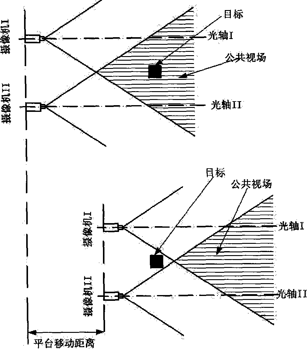
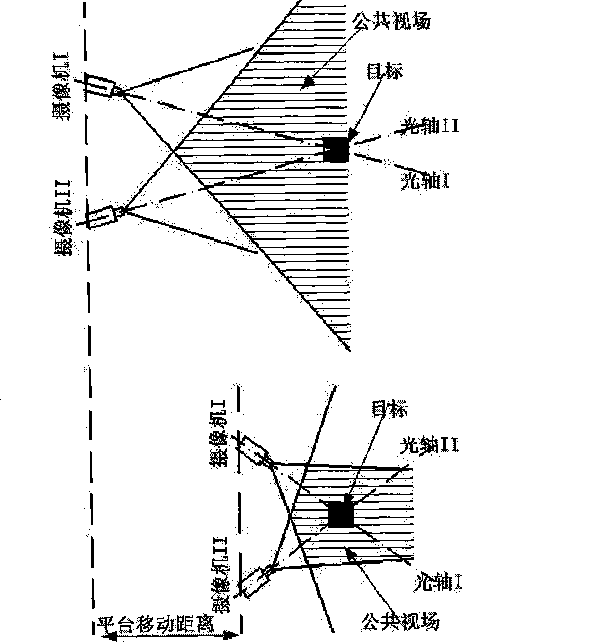
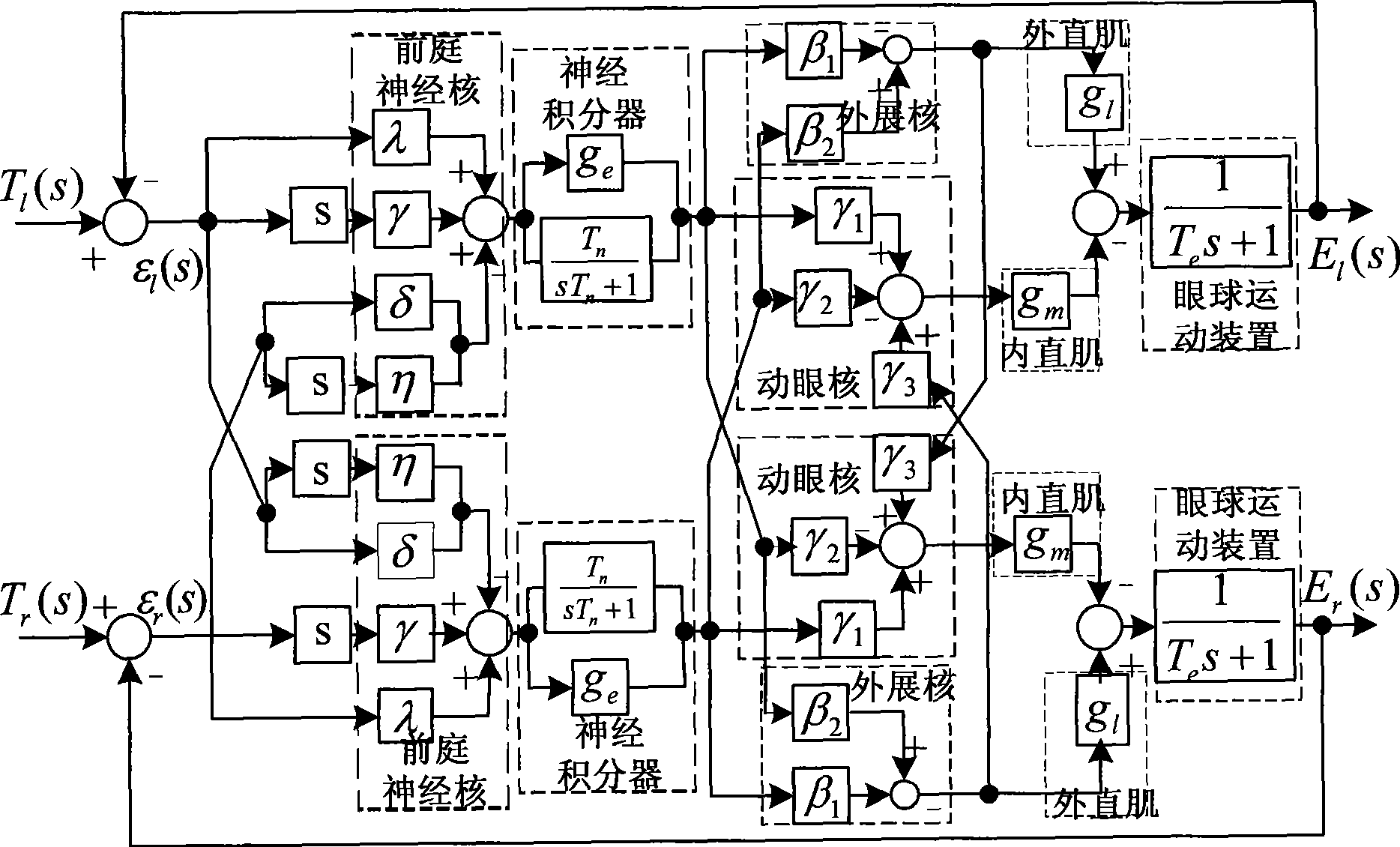
[0027] A preferred embodiment of the present invention is described in detail as follows: see Figure 5 , this method is based on the principle of anisotropic movement of bionic eyes to reduce the blind area of ​​the dual-camera monitoring system on the motion platform. The angle and direction of the dual cameras make the target area always in the common field of view of the two cameras, so as to obtain the three-dimensional depth information of the target area. Its control operation steps are as follows:

[0028] 1) Sensor measurement: measure the camera motion platform and the position parameters of the measured target;

[0029] 2) A / D conversion: A / D conversion is performed on the continuous analog quantity obtained by the sensor to obtain a digital quantity;

[0030] 3) Digital filtering: smoothing the sampling signal, enhancing the effective signal, eliminating or reducing noise;

[0031] 4) Scale conversion: Calibrate the sensor to obtain the input value corresponding...


PUM


Abstract

The invention relates to a method for reducing a fade zone by a twin camera monitoring system on a movement platform. When the movement platform loaded with the twin cameras generates the relative position changes with a target area, the method controls the angle and direction of the twin cameras based on the principle of the heterodromous motion of human eyeballs to cause that the target area is always in the public field of view of the twin cameras, thus obtaining the three dimensional depth information of the target area. In the method, after a sensor measures the movement parameters of the movement platform, A / D conversion, digital filtering, calibration conversion, and controlling operation are carried out on the parameters by a camera control unit, and then when a motor of a camera holder compensates the movement of the platform, the angle and direction needing to be rotated is obtained. A control signal drives the rotation of the motor of the camera holder on the movement platform by a serial port. By using the method for simple operation, the motor of the camera holder can be controlled to rotate according to a corresponding direction in a certain speed and the blind zone caused by the movement of the system loading with the camera platform is eliminated.

Description

technical field [0001] The present invention relates to a method for autonomously reducing blind spots when two cameras on a moving platform obtain depth information, and in particular to a method for reducing blind spots by controlling the movement of two cameras on a moving platform by using the principle of anomalous movement of human eyeballs . Background technique [0002] In systems such as monitoring and visual distance measurement and positioning, it is necessary to obtain real-time and accurate three-dimensional depth information. As we all know, in order to obtain accurate and real-time three-dimensional depth information, it is necessary to ensure that the measured target is always in the common field of view of the two cameras. However, For some situations where the camera needs to be installed on the motion platform, the traditional dual-camera surveillance ranging system has a blind spot, which cannot keep the target area in the public field of view all the tim...

Claims


Application Information

Patent Timeline
Patent Type & Authority Applications(China)
IPC IPC(8): H04N5/232H04N13/00
Inventor 李恒宇罗均谢少荣王涛陈平伟潘智昊夏冰玉
Owner SHANGHAI UNIV
Why Eureka
Try Eureka