Reconfigurable payload using non-focused reflector antenna for hieo and geo satellites

a technology of reflector antenna and hieo satellite, which is applied in the field of reconfigurable payloads for high-inclination elliptical orbit (hieo) and geostationary orbit (geo) communication satellites, can solve the problems of insufficient gain of such antennas for many applications, increased mass and expense of the approach, and reliability problems

Active Publication Date: 2007-08-09
LOCKHEED MARTIN CORP
View PDF6 Cites 12 Cited by
  • Summary
  • Abstract
  • Description
  • Claims
  • Application Information

AI Technical Summary

Benefits of technology

[0012] According to yet another embodiment, the present invention is a method for generating and configuring at least one defocused beam using an antenna system including a reflector having non-parabolic curvature and a plurality of feed antennas disposed in a focal plane of the reflector, the reflector including a single-axis gimbal mechanism. The method includes the step of dividing at least one incoming signal with at least one incoming signal dividing network into a plurality of sub-signals, each sub-signal corresponding to one of the plurality of feed antennas. The method further includes the step of phase shifting the plurality of sub-signals with a plurality of variable phase shifters, each variable phase shifter receiving one of the plurality of sub-signals from the at least one incoming signal dividing network and phase shifting the one of the plurality of sub-signals to generate a corresponding phase-shifted sub-signal. The method further includes the step of amplifying the plurality of phase-shifted sub-signals with a plurality of fixed-amplitude amplifiers, at least one amplifier corresponding to each of the plurality of feed antennas. The at least one amplifier for each feed antenna amplifies a corresponding phase-shifted sub-signal to generate an amplified phase-shifted sub-signal which is provided to the corresponding feed antenna. The method further includes the step of illuminating the reflector with the plurality of feed antennas to generate the at least one defocused beam. The plurality of variable phase shifters phase shift the plurality of sub-signals to compensate for a yawing motion of the antenna system. The single-axis gimbal mechanism of the reflector gimbals the reflector to compensate for a rolling motion of the antenna system.

Problems solved by technology

This approach suffers from reliability problems because the reconfiguration is mechanical.
Moreover, the gain of such an antenna is insufficient for many applications.
Because of the large number of elements, this approach suffers from increased mass and expense.
Moreover, this approach is unsuitable for handling large power loads due to the fact that the large number of amplifiers required can not be accommodated on a spacecraft.
Other limitations include the difficulty of power dissipation and very high cost.
Further, because the basic reflector geometry is de-optimized, the system suffers from increased scan losses, inferior cross-polar performance, mutual coupling effects and the like.
Moreover, the number of optical and other elements required is still undesirably large, and the system requires complex input and output hybrid matrices.

Method used


Image

  • Reconfigurable payload using non-focused reflector antenna for hieo and geo satellites
  • Reconfigurable payload using non-focused reflector antenna for hieo and geo satellites
  • Reconfigurable payload using non-focused reflector antenna for hieo and geo satellites

Examples


Embodiment Construction

[0027] In the following detailed description, numerous specific details are set forth to provide a full understanding of the present invention. It will be apparent, however, to one ordinarily skilled in the art that the present invention may be practiced without some of these specific details. In other instances, well-known structures and techniques have not been shown in detail to avoid unnecessarily obscuring the present invention.

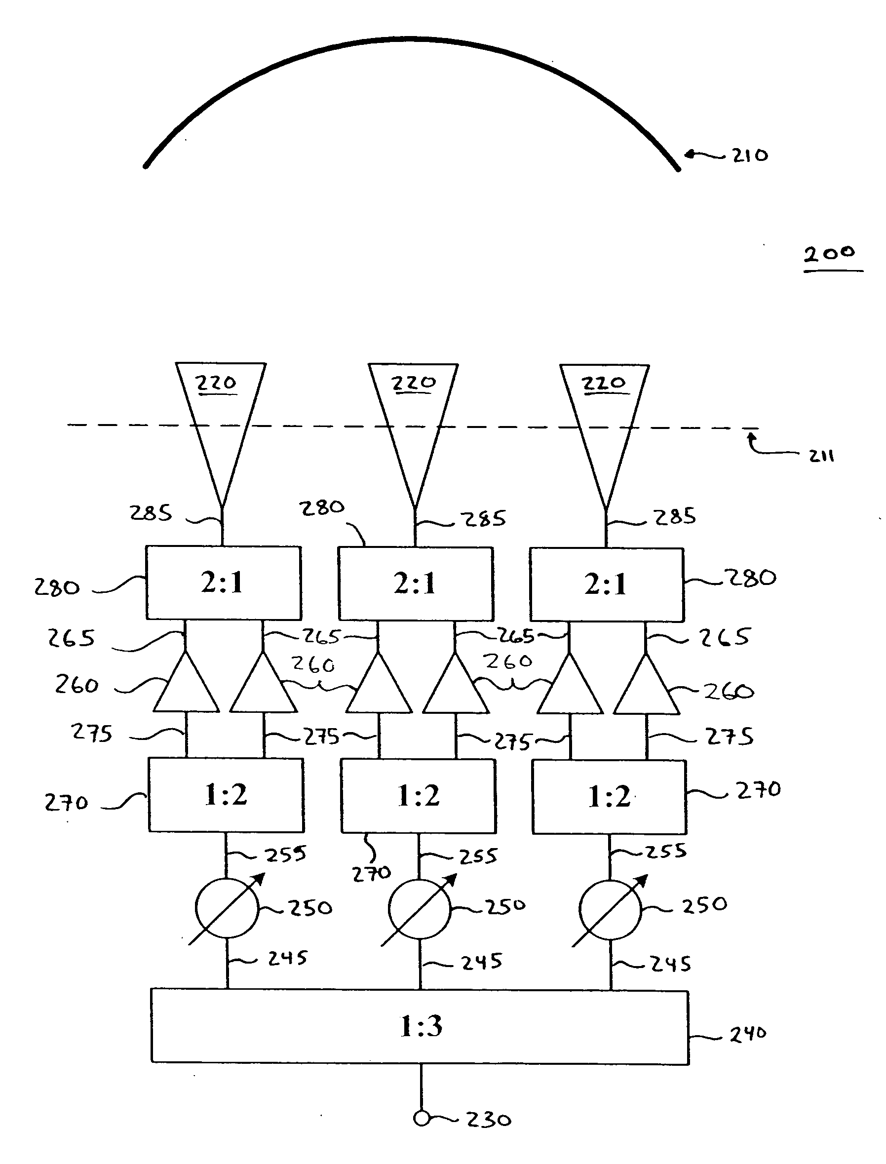
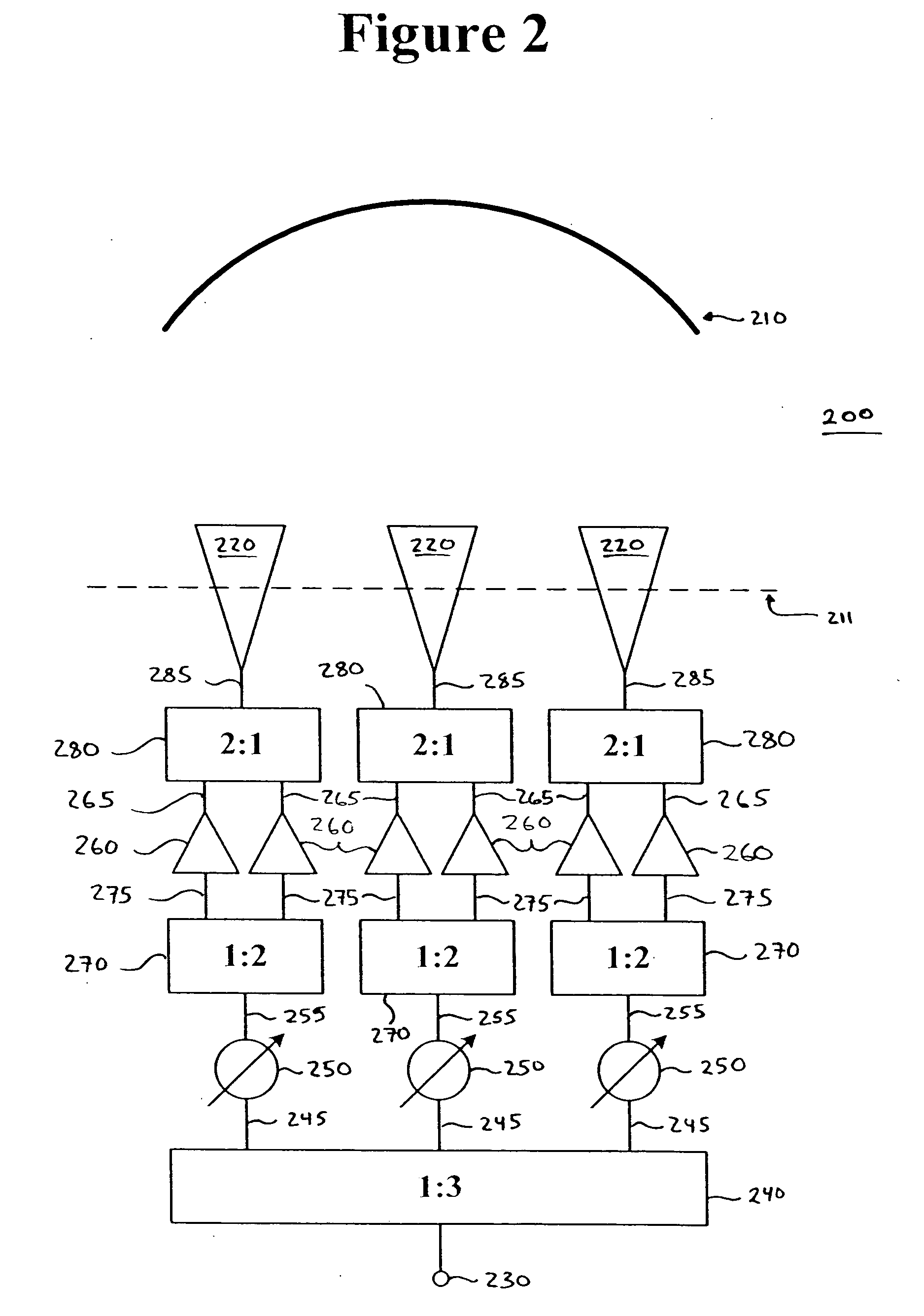
[0028]FIG. 1 illustrates an antenna system for generating and configuring at least one defocused beam according to one embodiment of the present invention. Antenna system 100 includes a reflector 110 having a non-parabolic curvature for forming one or more defocused beams. A plurality of feed antennas 120 are disposed in the focal plane 111 of reflector 110. The feed antennas 120 illuminate reflector 110 to generate the one or more defocused beams in the following manner.

[0029] An incoming signal 130 is divided by an incoming signal dividing network 14...


PUM


Abstract

An antenna system for generating and configuring at least one defocused beam is provided. The antenna system includes a reflector having a focal plane and a non-parabolic curvature for forming the at least one defocused beam, and a plurality of feed antennas that illuminate the reflector. Each feed antenna is disposed in the focal plane of the reflector. The antenna system further includes at least one incoming signal dividing network that divides at least one incoming signal into a plurality of sub-signals, each corresponding to one of the feed antennas, a plurality of variable phase shifters, each receiving one of the sub-signals from the incoming signal dividing network and phase shifting the sub-signal to generate a corresponding phase-shifted sub-signal, and a plurality of fixed-amplitude amplifiers, at least one corresponding to each of the feed antennas. The at least one amplifier for each feed antenna amplifies the corresponding phase-shifted sub-signal to generate an amplified phase-shifted sub-signal which is provided to the corresponding feed antenna.

Description

CROSS-REFERENCE TO RELATED APPLICATION [0001] The present application claims the benefit of priority under 35 U.S.C. §119 from U.S. Provisional Patent Application Ser. No. 60 / 758,674 entitled “RECONFIGURABLE PAYLOAD USING NON-FOCUSED REFLECTOR ANTENNA FOR HIEO AND GEO SATELLITES,” filed on Jan. 13, 2006, the disclosure of which is hereby incorporated by reference in its entirety for all purposes.STATEMENT REGARDING FEDERALLY SPONSORED RESEARCH OR DEVELOPMENT [0002] Not applicable. FIELD OF THE INVENTION [0003] The present invention generally relates to spacecraft payloads and, in particular, relates to reconfigurable payloads for highly inclined elliptical orbit (HIEO) and geostationary orbit (GEO) communication satellites. BACKGROUND OF THE INVENTION [0004] Satellites with reconfigurable payloads provide desirable on-orbit mission flexibility. A reconfigurable payload allows a satellite to change the shape and location of its beams in order to change earth coverage regions. These c...

Claims


Application Information

Patent Timeline
Patent Type & Authority Applications(United States)
IPC IPC(8): H01Q13/00
CPCH01Q19/10H01Q25/007H01Q19/17H01Q19/12
Inventor RAO, SUDHAKAR K.PECK, STEPHEN R.TANG, MINHWANG, JIMBROWN, DAVID M.
Owner LOCKHEED MARTIN CORP
Why Eureka
Try Eureka