Systems for linear mapping of lumens

a technology of linear mapping and lumens, applied in the direction of angiography, instruments, image enhancement, etc., can solve the problems of inability to accurately judge the actual length of the stent, the treatment is delivered without preserving position, and the existing mechanism to determine if the stent is positioned correctly

Inactive Publication Date: 2015-09-03
ANGIOMETRIX CORP
View PDF2 Cites 13 Cited by
  • Summary
  • Abstract
  • Description
  • Claims
  • Application Information

AI Technical Summary

Benefits of technology

[0007]Disclosed are efficient methods to create a linearized view of a body lumen with the help of multiple image frames. In reality a lumen has a trajectory in 3-D, but only a 2-D projected view is available for viewing. The linearized view unravels this 3-D trajectory thus creating a linearized map for every point on the lumen trajectory as seen on the 2-D display. In one mode of the invention, the trajectory is represented as a linearized display along 1-dimension. This linearized view is also combined with lumen measurement data and the result is displayed concurrently on a single image referred to as the analysis mode. This mode of operation can assist an interventionalist in uniquely demarcating a lesion, if there are any, and identify its position. Analysis mode of operation also helps in linearizing the blood vessel while an endo-lumen device is inserted in it (or manually pulled back) as opposed to the popularly used technique of motorized pullback. In another mode of the invention, the position of a treatment device is displayed on the linearized map in real time referred to as the guidance mode. Additionally, the profile of the lumen dimension is also displayed on this linearized map.

Problems solved by technology

While IVUS and OCT give a good estimate of the length and cross-sectional area of a lesion, one problem is that when the treatment is delivered it does not preserve position.
There is no existing mechanism to determine if the stent is positioned correctly at the diseased site.
The other problem is that the primary display used by physicians to view the X-ray images during diagnosis and treatment is typically a 2-D image taken from a certain angle and with a certain zoom factor.
This makes it difficult to accurately judge actual lengths from an X-ray image.
Even in this latter case, it is not practically possible to avoid the need for motion compensation even if the 2-D projection from a chosen phase of the heartbeat is used.
Secondly, because images are captured at discrete points in time (e.g., at 15 frames per second), there may not be a frame available at precise time instance of a particular phase of the heartbeat.
Thirdly, choosing only one phase of the heartbeat causes a large time gap between two successive frames chosen for a particular phase of the heartbeat.
This would make it very difficult to track moving markers on the device.

Method used


Image

  • Systems for linear mapping of lumens
  • Systems for linear mapping of lumens
  • Systems for linear mapping of lumens

Examples


Embodiment Construction

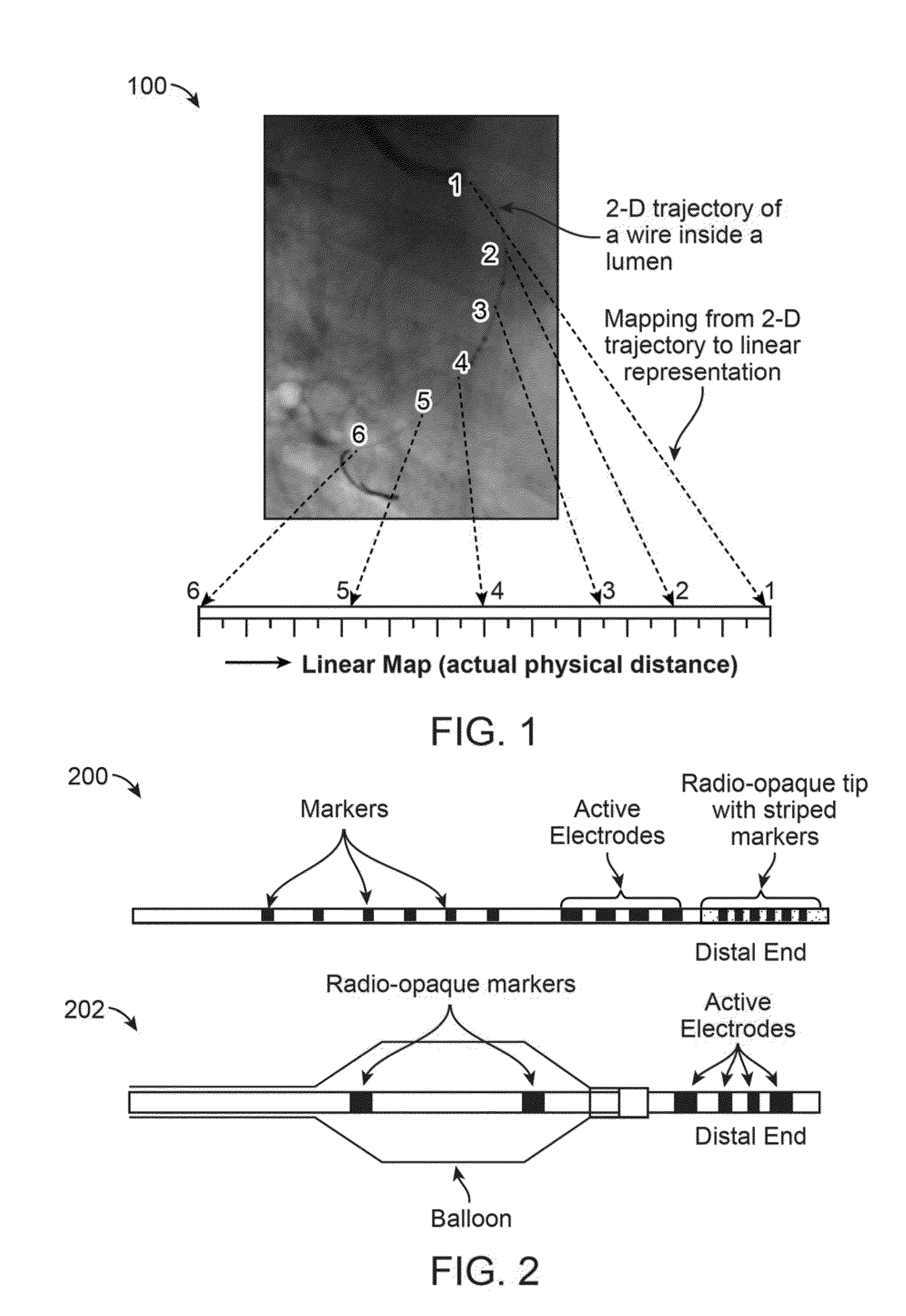
[0056]Here we describe methods to process the 2-D images to arrive at a linearized representation of a lumen of a moving organ. Illustrations of the proposed methods are shown for intervention of the coronary artery. A linear map is a mapping from a point on the curved trajectory of a lumen (or the wire inserted into the lumen) to actual linear distance measured from a reference point. This is shown in the schematic 100 in FIG. 1.

[0057]Note that in some sections of the blood vessel, the actual lumen trajectory in 3-D may be curving into the image (i.e. it subtends an angle to the viewing place). In these cases, an apparently small section of the lumen in the 2-D curved trajectory may map to a large length in the linear map. The linear map represents the actual physical distance traversed along the longitudinal axis of the lumen when an object traverses through the lumen.

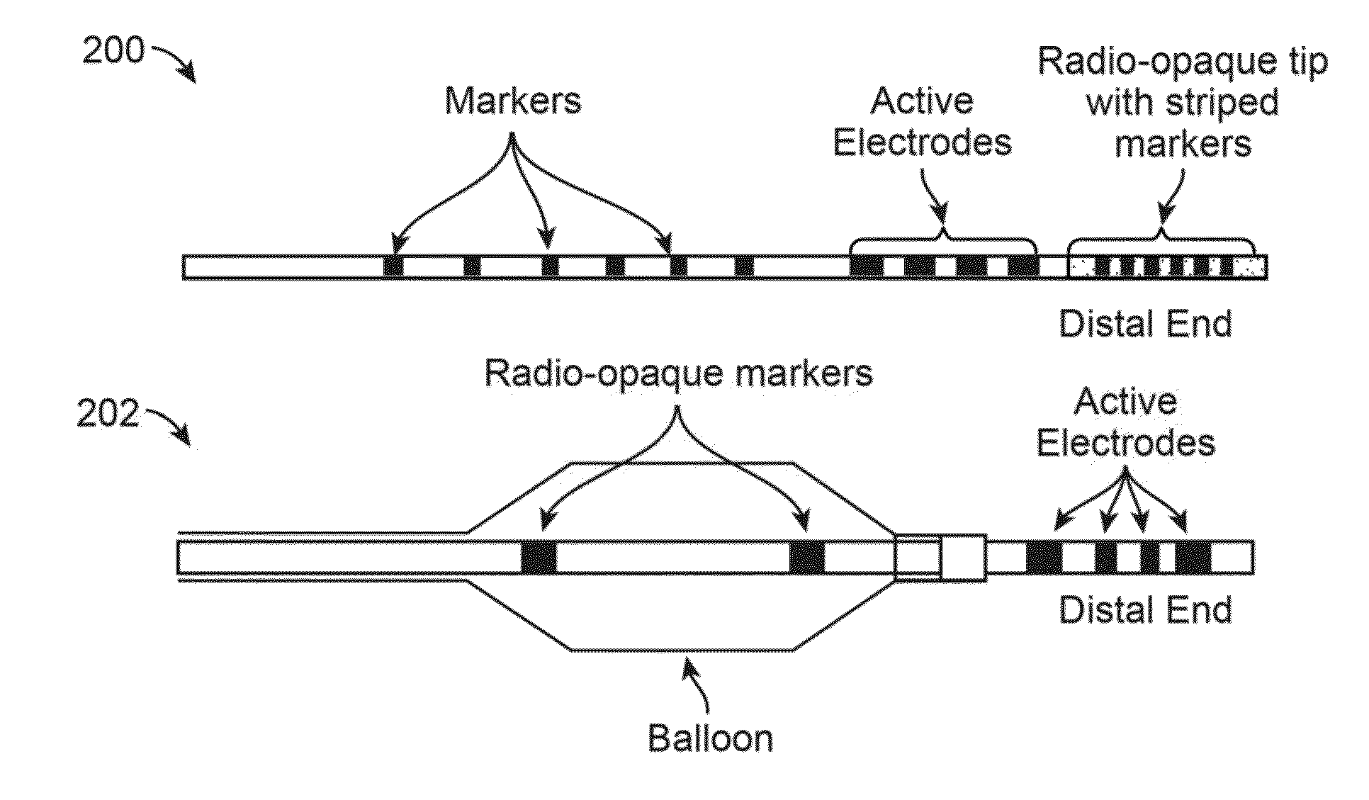
[0058]The linear mapping method is applicable in a procedure using any one of the following endo-lumen instruments...


PUM


Abstract

Systems for linear mapping of lumens are described which utilizes methods to create a linearized view of a lumen using multiple imaged frames. In reality a lumen has a trajectory in 3-D, but only a 2-D projected view is available for viewing. The linearized view unravels this 3-D trajectory thus creating a linearized map for every point on the lumen trajectory as seen on the 2-D display. In one mode of the invention, the trajectory is represented as a linearized display along 1 dimension. This linearized view is also combined with lumen measurement data and the result is displayed concurrently on a single image. In another mode of the invention, the position of a treatment device is displayed on the linearized map in real time. In a further extension of this mode, the profile of the lumen dimension is also displayed on this linearized map.

Description

CROSS-REFERENCE TO RELATED APPLICATIONS[0001]This application is a continuation of International Application No. PCT / US2013 / 039995 filed May 7, 2013, which claims the benefit of priority to U.S. Provisional Application No. 61 / 644,329 filed May 8, 2012 and 61 / 763,275 filed Feb. 11, 2013, each of which is incorporated herein by reference in its entirety.FIELD OF THE INVENTION[0002]The invention relates generally to intravascular medical devices. More particularly, the invention relates to guidewires, catheters, and related devices which are introduced intravascularly and utilized for obtaining various physiological parameters and processing them for mapping of various lumens.BACKGROUND OF THE INVENTION[0003]There are several devices such as IVUS and OCT wires or catheters that measure dimensions of lumens. These devices are inserted into the lumen to the end of or just past the region of interest. The device is then pulled back using a stepper motor while lumen measurements are made. ...

Claims


Application Information

Patent Timeline
Patent Type & Authority Applications(United States)
IPC IPC(8): A61B19/00A61B1/00A61M5/00A61M25/10A61M25/09
CPCA61B19/54A61B2019/5425A61M25/09A61M5/007A61B19/5244A61B1/00009A61M2025/09166A61B2019/5291A61B2019/5251A61B2019/5287A61B2019/5265A61B2019/5238A61B2019/5236A61B2019/5276A61B2019/5231A61B2019/5295A61M2025/1079A61B2019/5466A61B2019/5454A61B2019/5479A61M25/10A61B6/12A61B6/487A61B6/503A61B6/504A61B6/5264A61B6/5288G06T7/246G06T2207/30021G06T2207/10016G06T2207/10116A61B2090/373A61B2090/363A61B2090/367A61B2090/3979A61B34/20A61B2090/376A61B2090/374A61B2034/2051A61B2034/2065A61B2090/378A61B2090/365A61B90/39A61B2090/3925A61B2090/3954A61B2090/3966A61B1/000096
Inventor VENKATRAGHAVAN, VIKRAMSUBRAMANIYAN, RAGHAVAN
Owner ANGIOMETRIX CORP
Why Eureka
Try Eureka