Electrical heating apparatus, method of manufacturing heat generator unit and pressing jig

A technology of electric heating device and heating unit, which is applied in the field of pressure fixtures, and can solve the problems of inability to complete power supply and heat generation, increase in cost and weight, and inability to obtain contact pressure, etc.

Inactive Publication Date: 2009-04-29
CALSONIC KANSEI CORP
View PDF1 Cites 12 Cited by
  • Summary
  • Abstract
  • Description
  • Claims
  • Application Information

AI Technical Summary

Problems solved by technology

[0005] As in the above-mentioned prior art, when the contact pressure between the electrode plate and the tube body of the energized heating element such as the PTC element is lower than the set pressure, the heat generation and heat dissipation cannot be completed smoothly, and sufficient heat generation cannot be obtained.
In other words, when the contact pressure between the energized heating element and the tube body is low, the heat generated by the energized heating element cannot be smoothly transferred to the tube body. At this time, the temperature of the energized heating element itself becomes high, and the resistance value increases. , energization and heating cannot be completed smoothly
[0006] Therefore, in the case where an urging member such as a spring is provided to ensure the contact pressure between the energized heating element and the pipe body, the number of parts increases, leading to an increase in cost and weight
[0007] On the other hand, in order to ensure the contact pressure between the pipe body and the electric heating element, the pipe body can be stamped, but in this case, in order not to damage or overload the electric heating element housed inside, press processing is difficult
In addition, when the ener

Method used


Image

  • Electrical heating apparatus, method of manufacturing heat generator unit and pressing jig
  • Electrical heating apparatus, method of manufacturing heat generator unit and pressing jig
  • Electrical heating apparatus, method of manufacturing heat generator unit and pressing jig

Examples


Embodiment 1

[0042] based on the following Figure 1 to Figure 7 The electrothermal device A of Example 1 which is the best mode for carrying out the present invention will be described.

[0043] The electrothermal device A of the first embodiment is used for heating and blowing air in, for example, a vehicle air-conditioning unit (not shown).

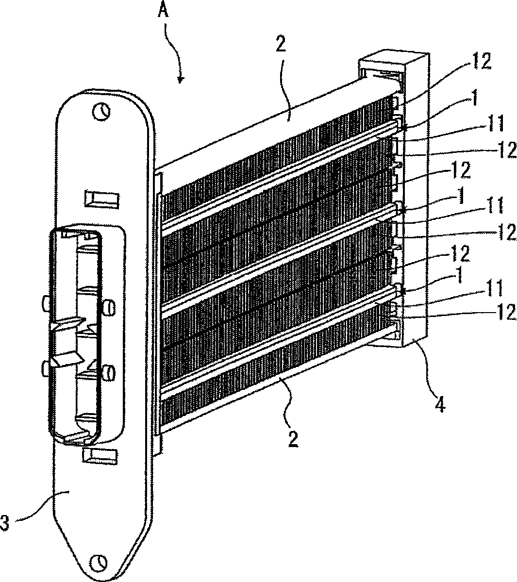
[0044] The electric heating device A is formed by stacking the heating units 1 described later in three layers along the vertical direction, then clamping them up and down with the end plates 2 and 2, and inserting the two longitudinal ends thereof into the front cover 3 and the end cover 4 to fix them.

[0045] The front cover 3 and the end cover 4 are formed of a material having excellent electrical insulation and heat resistance, such as fiber-reinforced PBT (polybutylene terephthalate: polybutylene terephthalate) or the like. The fiber-reinforced PBT exhibits excellent dimensional stability due to low water absorption and thermal expansion coe...

Embodiment 2

[0105] A method of manufacturing the heat generating unit according to Example 2 of the embodiment of the present invention will be described with reference to FIG. 8 .

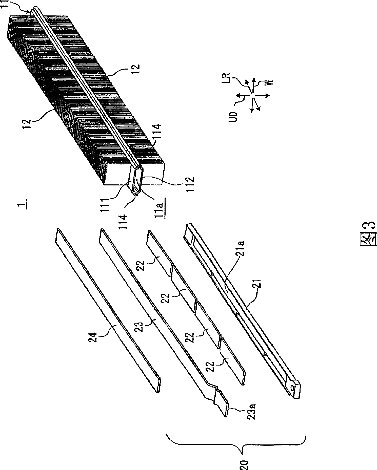
[0106] This second embodiment is an example in which a substantially rectangular cylindrical pipe member without an end portion 114 is used as the pipe body 201 of the heating unit 200 .

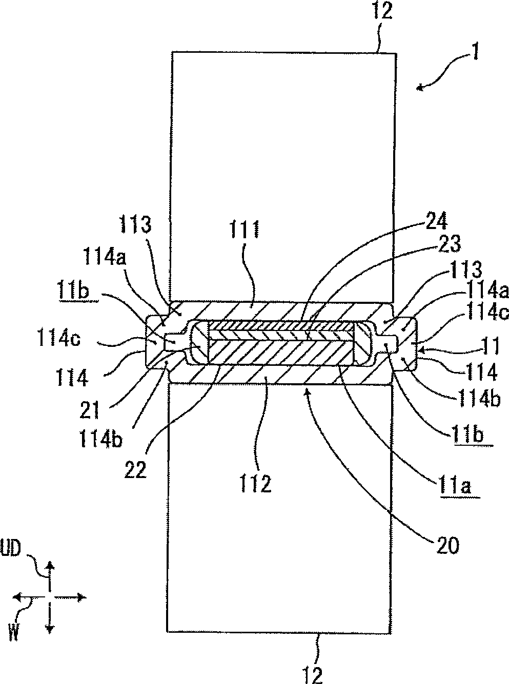
[0107] That is, the main body upper wall 202, the main body lower wall 203, and the main body vertical walls 204 and 205 of the pipe body 201 surround the insertion space 201a having a substantially rectangular cross-sectional shape and form a substantially rectangular cylindrical cross-sectional shape.

[0108] On the outer surface of the main body upper wall 202 and the main body lower wall 203, positioning grooves 206, 206, 206, 206 for positioning the heat sink 12 in the width direction are formed on the edge portions on both sides in the width direction. Raised ribs 207, 207, 207, 207.

[0109] On both sides in the wi...


PUM


Abstract

An electrical heating apparatus has: a fin brazed on at least one of a main body upper wall and a main body lower wall of a tube; an insertion unit having an electro-heat-generating element pressure-welded to a wall of one of the main body upper wall and the main body lower wall; and an edge part projected in the width direction from each of main body vertical walls to form an edge space. The edge space is formed so as to be continuous with the insertion space and is smaller in thickness dimension than the thickness dimension of the insertion unit.

Description

technical field [0001] The present invention relates to an electrothermal device including an energized heating element called a PTC (Positive Temperature Coefficient: Positive Temperature Coefficient) element that generates heat when energized, a method for manufacturing a heating unit, and a pressure jig. Background technique [0002] Conventionally, an electrothermal device in which a PTC element that generates heat when energized and a heat sink that dissipates the heat generated by the PTC element is laminated is known, for example, from Japanese Patent Application Laid-Open No. 5-169967. [0003] As such an electric heating device, the known structure is that the electrode plate and the insulating plate are stacked on the electric heating body in order to form an assembly contained in a conductive tube body, and then the heat sink is crimped or bonded to the tube body. on the outside. [0004] In this kind of electric heating device, the electrode plate and the heat s...

Claims


Application Information

Patent Timeline
IPC IPC(8): H05B3/50B60H1/22F24H3/04
Inventor 森和明阿部尚太郎
Owner CALSONIC KANSEI CORP
Why Eureka
Try Eureka