Method of preheating injectors of internal combustion engines

A technology for injectors and internal combustion engines, which is applied to fuel injection devices, special fuel injection devices, machines/engines, etc., can solve problems such as damage to the function of the injection system, and achieve the effect of ensuring normal operation.

Active Publication Date: 2009-04-29
ROBERT BOSCH GMBH
View PDF4 Cites 10 Cited by
  • Summary
  • Abstract
  • Description
  • Claims
  • Application Information

AI Technical Summary

Problems solved by technology

This prevents the highly viscous fuel from cooling down in the injector and impairs the function of the injection system when the engine is started or renders it completely unusable

Method used


Image

  • Method of preheating injectors of internal combustion engines
  • Method of preheating injectors of internal combustion engines
  • Method of preheating injectors of internal combustion engines

Examples


Embodiment Construction

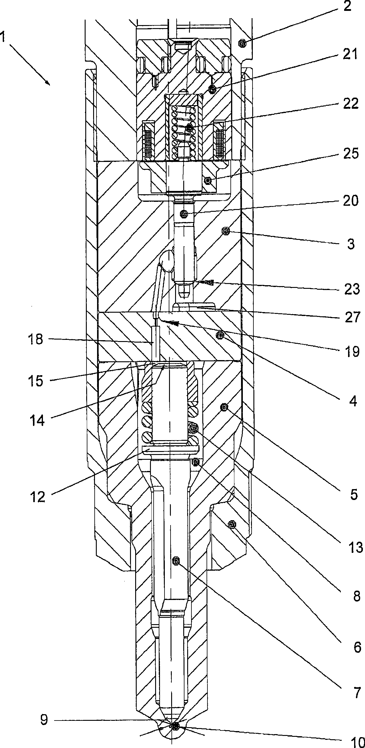
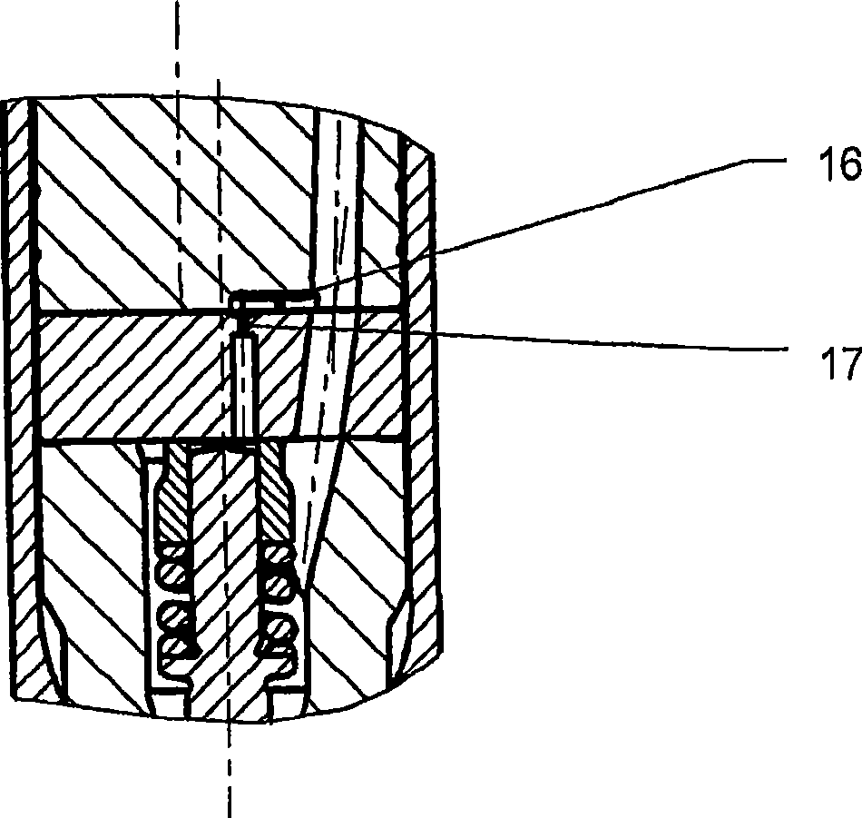
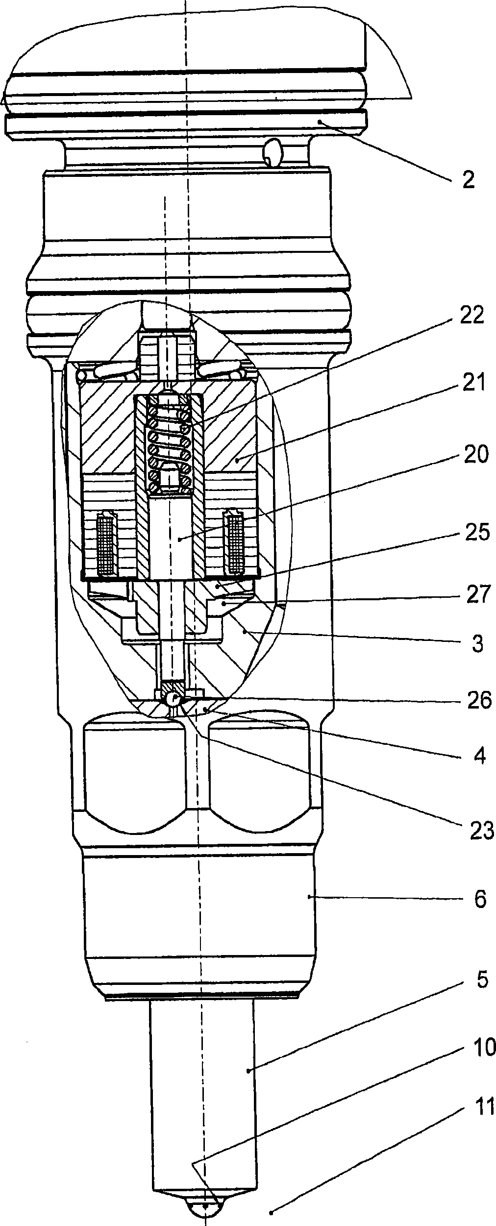
[0015] in figure 1 with 2 An injector 1 is shown from the injector base 2, a valve group or valve 3, an intermediate plate 4, an injector nozzle 5, and a nozzle tension nut 6. The injector nozzle 5 includes a nozzle needle 7 that slidably guiled in the injector nozzle 5 and has a plurality of free surfaces, and the fuel can flow from the nozzle tip 9 from the nozzle front chamber 8. When the nozzle 7 is opened, the fuel is injected into the combustion chamber 11 through the at least one ejection hole 10. On the nozzle needle 7, a shoulder 12 is provided on the circumference, and the compression spring 13 is supported on the shoulder, the spring applies a closed force on the nozzle needle 7. The nozzle needle 7 ends in the end surface 14 in the end surface 14 on one side opposite to the nozzle needle tip 9, which ends in the control chamber 15. The control chamber 15 has an input channel 16 with input throttle valve 17 and an overflow channel 18 with an overflow throttle valve 19....


PUM


Abstract

In a method and a device for preheating injectors (1), having at least one valve (3) which can be activated by an electromagnet (21), of internal combustion engines, in which the coil of the electromagnet (21) is energized before the engine is started, a preheating voltage (42) is periodically applied to the coil of the electromagnet (21), and the current characteristic (33) in the coil is monitored and evaluated in order to detect local current minima (43) and / or current maxima (44) caused by armature reactions.

Description

Technical field [0001] The present invention relates to a method and apparatus for a preheating internal combustion engine, wherein the injector has at least one valve that can be controlled by an electromagnet, wherein the coil of the electromagnet is powered by the engine starts. Background technique [0002] In principle, the injection system, especially the injector of the common rail diesel injection system consists of a plurality of parts that are typically fixed together by the nozzle tension nut. A nozzle needle is slidably guided by a plurality of free surfaces in the base body of the original injector nozzle, and the fuel can flow from the nozzle tip from the nozzle front room via the free surface. A sealing valve seat is typically present in the nozzle tip, which prevents the fuel from reaching the combustion chamber in the case of a closed nozzle needle. The nozzle needle has a shoulder on the circumference, and the compression spring supported on the nozzle needle is...

Claims


Application Information

Patent Timeline
Patent Type & Authority Applications(China)
IPC IPC(8): F02M51/06F02M53/04F02M53/06
CPCF02M53/04F02M53/06F02M51/061Y10T137/6606F02M2200/248
Inventor J·洛塞克G·雷比克勒J·施尼特
Owner ROBERT BOSCH GMBH
Why Eureka
Try Eureka