Air conditioning apparatus

An air-conditioning device and air-conditioning technology, which is applied in the directions of air-conditioning system, space heating and ventilation, space heating and ventilation details, etc., can solve the problems of unsightly appearance and neglecting the appearance of air outlet.

Inactive Publication Date: 2009-04-29
DAIKIN IND LTD
View PDF1 Cites 12 Cited by
  • Summary
  • Abstract
  • Description
  • Claims
  • Application Information

AI Technical Summary

Problems solved by technology

[0006] However, the air conditioner described in the above-mentioned Patent Document 1 focuses on thinning and reducing air blowing resistance, but i

Method used


Image

  • Air conditioning apparatus
  • Air conditioning apparatus
  • Air conditioning apparatus

Examples


Embodiment Construction

[0124]

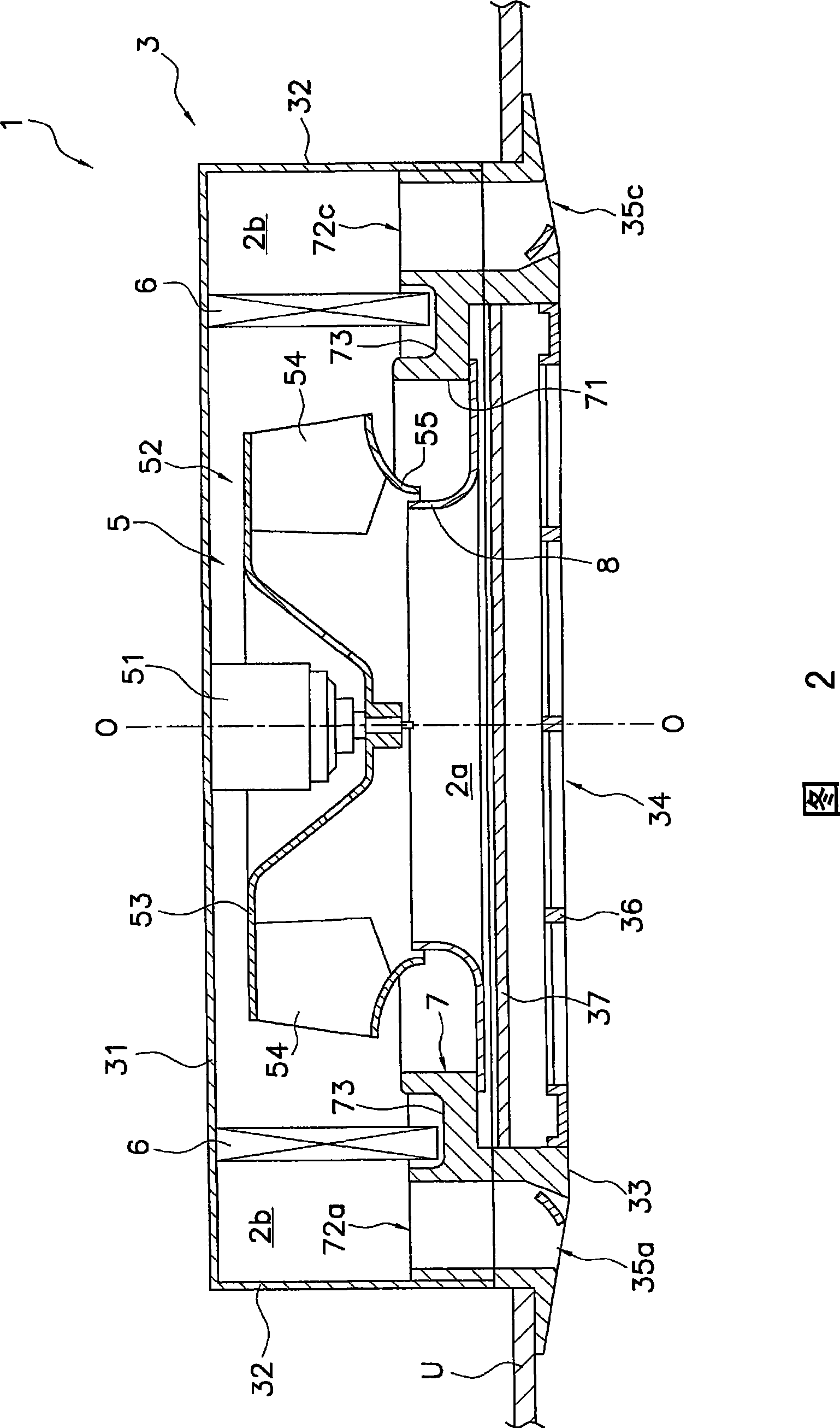
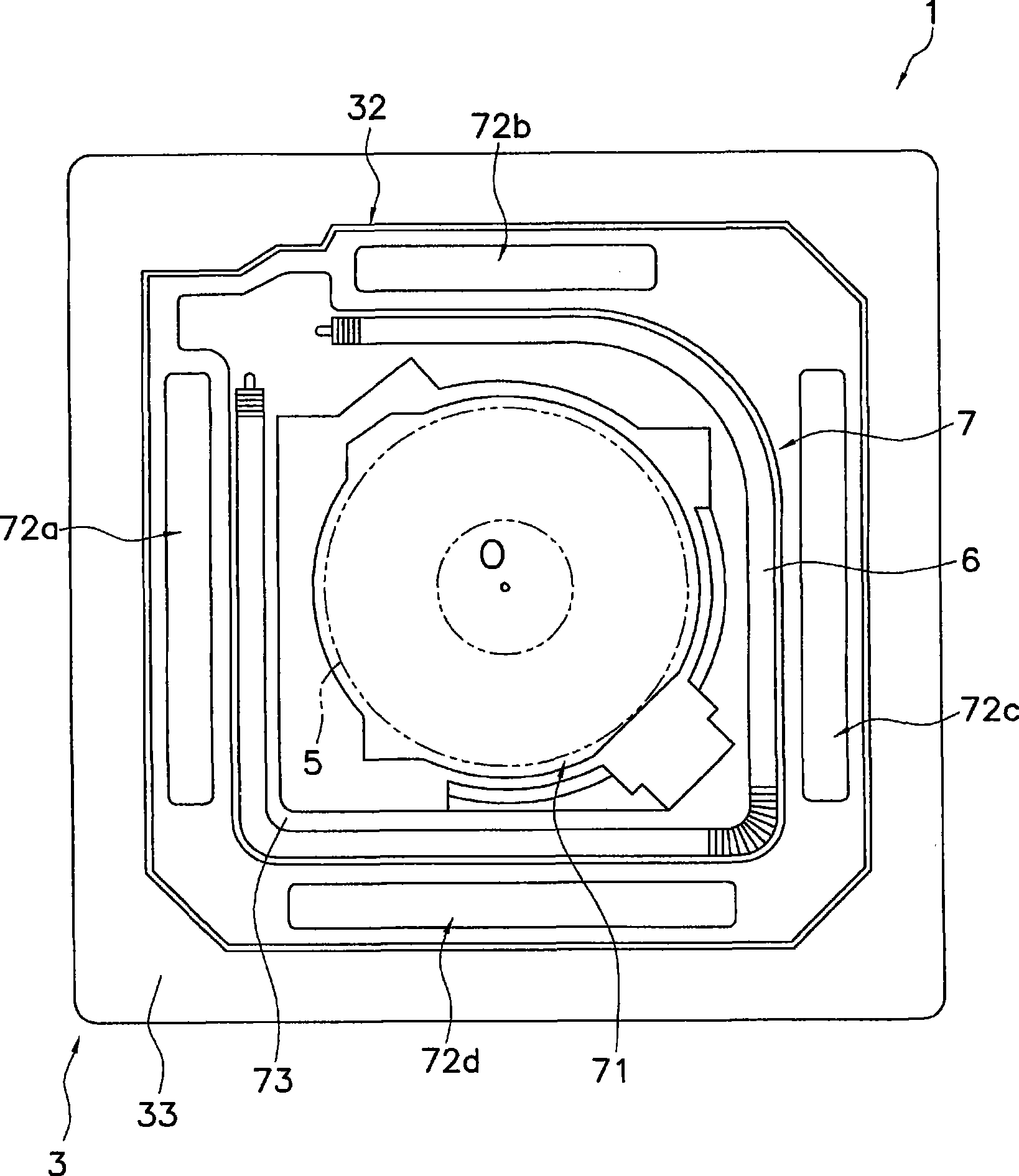
[0125] The present invention provides an air conditioner in which a suction port appears by moving a panel. The air conditioner according to the present invention has a structure in which the suction port is covered with a substantially planar panel in a non-operating stop state. That is, in the state where the suction port is covered, the substantially planar panel can be seen mainly in appearance, and the opening and concave-convex part are not easy to be seen, which is very simple. The present invention is characterized in that the appearance of the air conditioner can be improved thereby. In addition, the present invention is also characterized in that the panel and the entire peripheral portion can be moved together by the opening and closing mechanism to make the suction port appear, thereby ensuring sufficient ventilation.

[0126] Next, various embodiments of the ceiling-mounted air conditioner of the present invention will be described with reference to th...


PUM


Abstract

An air conditioning apparatus includes a casing and a dividing cosmetic panel. The casing has a suction port and a discharge port. The dividing cosmetic panel has a plurality of dividing panels and an opening/closing moveable mechanism for varying the positions of the dividing panels relative to the suction port. The opening/closing moveable mechanism switches between a state in which the dividing panels are disposed in proximity to each other, thereby blocking air flow through the suction port, and a state in which the dividing panels are separated from each other to allow ventilation through the suction port.

Description

technical field [0001] The present invention relates to an air conditioner, and more particularly to an air conditioner installed and used near a ceiling. Background technique [0002] In the past, for example, there is known an indoor unit of an air conditioner that sucks in indoor air and then supplies conditioned air to the room. Like indoor units such as ceiling-embedded indoor units, a flat plate is formed so that the air outlet and the air inlet are along the ceiling surface. configuration. [0003] Such an indoor unit needs to be thinned due to restrictions on the installation space near the ceiling, etc., and the internal air blowing resistance tends to increase. [0004] In this regard, for example, in the air conditioner described in Patent Document 1 shown below, it is proposed to adopt a structure that makes the flow velocity distribution inside the indoor unit as uniform as possible, and to reduce the thickness of the air conditioner while suppressing the air b...

Claims


Application Information

Patent Timeline
IPC IPC(8): F24F13/20F24F13/15
CPCF24F2001/0037F24F13/12F24F1/0011F24F13/072F24F2013/0616F24F1/0047F24F13/20F24F13/15
Inventor 藪知弘
Owner DAIKIN IND LTD
Why Eureka
Try Eureka