
Divert ball joint assembly

A steering ball and assembly technology, applied in steering mechanism, steering rod, transportation and packaging, etc., can solve the problem of shortening the service life of the steering ball joint assembly, affecting the service life of the steering ball joint assembly, and manufacturing the steering ball joint assembly. The problem of high cost, to achieve the effect of improving the safety index, good elastic performance, and reducing the manufacturing cost

Inactive Publication Date: 2009-05-06
许建红
View PDF0 Cites 3 Cited by
  • Summary
  • Abstract
  • Description
  • Claims
  • Application Information

AI Technical Summary

Problems solved by technology

However, a fatal weakness of the steering ball joint assembly with the above structure is that it requires extremely high elastic performance of the spring, so the corresponding manufacturing cost of the steering ball joint assembly is relatively high; in addition, due to the limitation of the space of the ball head hole , the spring here cannot be made of very thick spring steel wire, therefore, the spring is very prone to breakage during the use of the steering ball joint assembly, especially when the steering ball joint assembly of this structure is used on a heavy truck The fracture occurs more frequently, which not only greatly shortens the service life of the steering ball joint assembly, but also reduces the safety index of its use; in addition, in the steering ball joint assembly of the above structure, the ball stud pin It is in direct contact with the ball seat, so its hard-to-hard hard surface wears faster, which directly affects the service life of the steering ball joint assembly

Method used


Image

  • Divert ball joint assembly

Examples


Embodiment Construction

[0011] The present invention will be further described below in conjunction with accompanying drawing and specific embodiment:

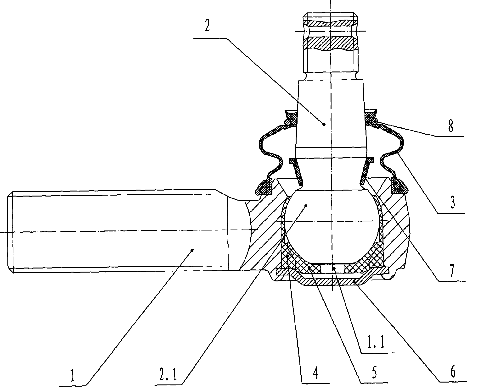
[0012] As shown in the drawings, in this specific embodiment, the present invention includes a ball seat 1, a ball stud 2, a dust cover 3, a wear-resistant bushing 4, an elastic bushing 5, and a ball seat 1 connected to the bottom for sealing. The gasket 6 that holds the ball head hole 1.1; the upper part of the dust cover 3 is fastened on the taper part of the ball stud 2 through the collar 7, and the lower part is fastened in the groove on the upper part of the ball seat 1; The ball head portion 2.1 of the ball stud pin 2 is located in the ball head hole 1.1 on the ball seat 1; the wear-resistant bushing 4 is connected to the entire inner wall of the ball head hole 1.1; the elastic bushing 5 is connected to the Below the inner wall of the wear-resistant bushing 4; the upper middle part of the ball head part 2.1 is in close contact with the wear-res...


PUM


Abstract

The invention discloses a steering ball joint assembly which comprises a ball seat (1), a ball stud (2), a dust shield (3), a wearable busing (4), an elastic busing (5) and a spacer (6) which is connected with the bottom part of the ball seat (1) and used for sealing a ball-end hole(1.1), wherein, the dust shield (3) is connected between the ball seat (1) and the ball stud (2); a ball-end part (2.1) of the ball stud (2) is positioned in a ball-end hole (1.1) of the ball seat (1); the wearable busing (4) is connected to the whole inner hole wall of the ball-end hole (1.1); the elastic busing (5) is connected with the lower part of the inner wall of the wearable busing (4); the middle-upper part of the ball-end part (2.1) is closely contacted with the wearable busing (4); and the lower part of the ball-end part (2.1) is closely contacted with the elastic busing (5). The steering ball joint assembly has the advantages that the manufacture cost is low, the structure is safer and more reliable, and the service life is greatly prolonged.

Description

Technical field: [0001] The invention relates to a ball joint assembly, in particular to a steering ball joint assembly with automatic compensation function used in an automobile steering system. Background technique: [0002] As we all know, the steering ball joint assembly is a key part in the steering system of the car. Its structure, performance and service life directly affect the steering flexibility of the car during driving and the safety of the car. At present, the traditional steering ball joint assembly includes a ball seat, a ball stud, a spring, a ball bowl, a dust cover and a sleeve; the ball seat is provided with a ball hole for placing the ball stud; the sleeve The sleeve is connected to the bottom of the ball hole; the sleeve is provided with a ball bowl; the spring is arranged between the inner bottom of the sleeve and the ball bowl; the ball head part of the ball stud pin is in close contact with the top of the ball bowl. In the steering ball joint assemb...

Claims


Application Information

Patent Timeline
Patent Type & Authority Applications(China)
IPC IPC(8): B62D7/18
Inventor 许建红秦德福
Owner 许建红
Learn More