
Fan

A fan and fan cover technology, which is applied in the field of fans, can solve the problems of easy damage and failure of switches and swing components, unfavorable long-term use of fans, and unfavorable appearance of fans, etc., and achieves the effects of wide practicability, beautiful appearance, and compact settings

Active Publication Date: 2009-05-06
KENNEDE ELECTRIONICS MFG CO LTD
View PDF0 Cites 6 Cited by
  • Summary
  • Abstract
  • Description
  • Claims
  • Application Information

AI Technical Summary

Problems solved by technology

The switch set above the rear case is not conducive to the overall beauty of the fan, and it is easy to allow dust to enter, and when the fan swings, because the gear connected to the switch is directly connected to the motor through a first-stage transmission, the switch will rotate with the motor Rotate together, so that the switch and swing components are easy to damage and fail, which is not conducive to the long-term use of the fan

Method used


Image

  • Fan
  • Fan
  • Fan

Examples


Embodiment Construction

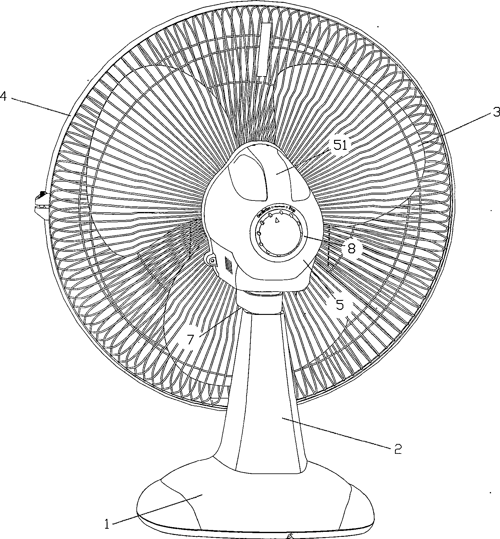
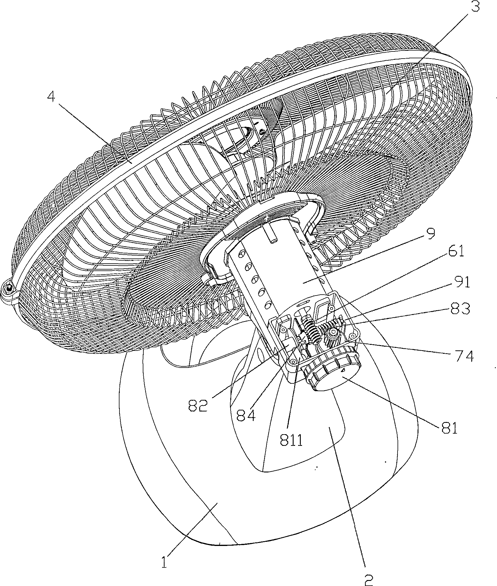
[0020] refer to figure 1 ~ Figure 3, a fan, including a base 1, a fixed bracket 2 installed on the base 1, a fan blade 3 located at the front end of the fan, a fan cover 4, a rear case 5 located at the rear end of the fan cover 4, and mounted on the rear case The motor group 6 in the 5, the fan swing device 7 and the swing switch device 8, the control switch button of the swing switch device 8 is installed on the rear surface of the rear housing 5.

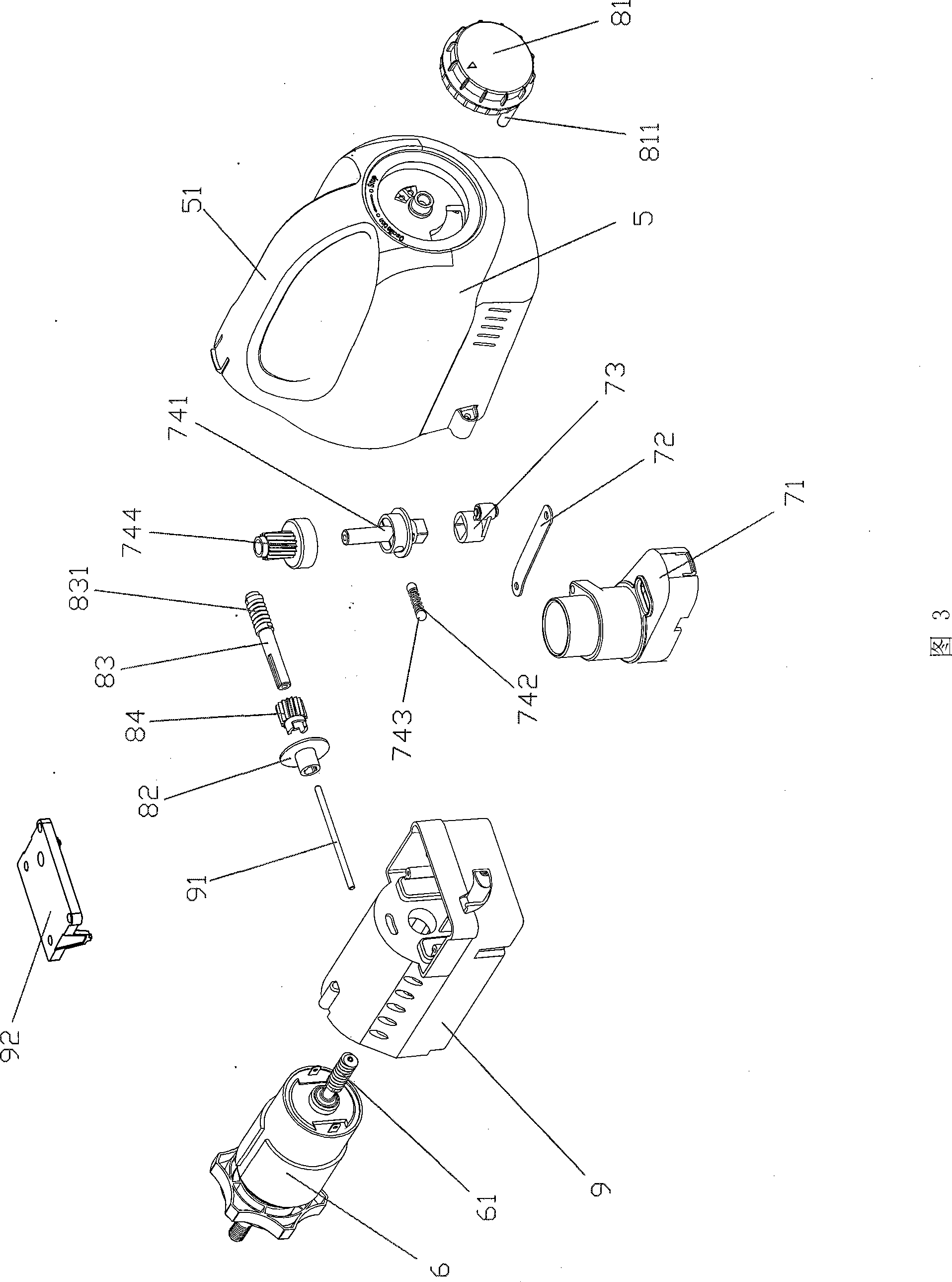
[0021] As a preferred mode of the present invention, the swing head switch device is a two-stage transmission mechanism, including: a two-stage transmission rod 83 installed transversely inside the rear housing 5, and the front part of the two-stage transmission rod 83 is connected to the motor group 6 through the clutch device. The output rotating worm screw 61 is transmission connected, and the rear part is driven and connected to the fan swing head device 7 through a gear set. The control switch button is a knob 81, and the fro...


PUM


Abstract

The invention discloses a fan. The fan comprises a base, a fixed bracket arranged on the base, and fan blades and a fan cover which are positioned in the front end of the fan, and a front cover plate and a rear shell which are positioned in the rear end of the fan, a motor set arranged inside the front cover plate and the rear shell, a fan head swinging device and a head swinging switch device; a control switch button of the head swinging switch device is arranged on the rear surface of the rear shell; as the control switch button of the fan head swinging device is arranged on the rear surface of the rear shell, the fan has attractive appearance and can also prevent dust; the matched structure of the head swinging device inside the fan is compact, novel, reasonable and simple in manufacturing so that the fan is durable and has attractive appearance and wide practicability.

Description

technical field [0001] The invention relates to a fan, in particular to a fan with a swing head switch arranged at the rear. Background technique [0002] At present, the fans on the market all have the function of swinging the head, generally including a base, a fixed bracket installed on the base, a fan blade and a fan cover located at the front end of the fan, a rear case located at the rear end of the fan cover, and a motor unit installed in the rear case And the fan swing head device, wherein, the switch for controlling the swing of the swing head device is installed above the rear casing, and the swing head of the fan is controlled by pulling up or pressing down the switch. The basic principle is that when the switch extends into the rear casing The part of the swing head is connected to the swing head device, and a clutch device is connected to the end. The clutch device can be connected or separated from the motor group through the gear. When the switch is pressed, t...

Claims


Application Information

Patent Timeline
Patent Type & Authority Applications(China)
IPC IPC(8): F04D25/10F04D29/00
Inventor 田畴
Owner KENNEDE ELECTRIONICS MFG CO LTD
Learn More