
Vertical self-priming pump and vertical self-priming pump with filtration device

A filtering device, self-priming technology, applied to pump devices, components of pumping devices for elastic fluids, non-displacement pumps, etc., can solve the problem of time-consuming and labor-intensive, dangerous, polluting operators or surrounding equipment and other problems, to achieve the effect of suppressing height and setting small space

Inactive Publication Date: 2009-05-06
WORLD CHEM CO LTD
View PDF3 Cites 6 Cited by
  • Summary
  • Abstract
  • Description
  • Claims
  • Application Information

AI Technical Summary

Problems solved by technology

[0005] However, the recovery of the liquid extracted from the drainpipe must be carried out manually with a bucket or the like, which is not only complicated but also dangerous depending on the type of liquid.
[0006] In addition, in the filter immersed in the liquid until the extraction of the liquid, even if the extraction of the liquid is performed, the liquid remaining on the surface of the filter or the liquid retention part in the mesh will flow down, so when it is taken out, not only will the It pollutes the operator or the surroundings of the equipment, and it is difficult to take out the filter where the liquid flows down, and the replacement operation is complicated and troublesome, and there are disadvantages that it may be dangerous depending on the type of liquid
[0007] Furthermore, when the operation is resumed after filter replacement, it is necessary to extract the air in the pump and fill water before starting, so not only time and labor are required, but also there is a disadvantage that the operation interruption time is prolonged.

Method used


Image

  • Vertical self-priming pump and vertical self-priming pump with filtration device
  • Vertical self-priming pump and vertical self-priming pump with filtration device
  • Vertical self-priming pump and vertical self-priming pump with filtration device

Examples


Embodiment Construction

[0102] The present invention will be described in detail below based on the accompanying drawings.

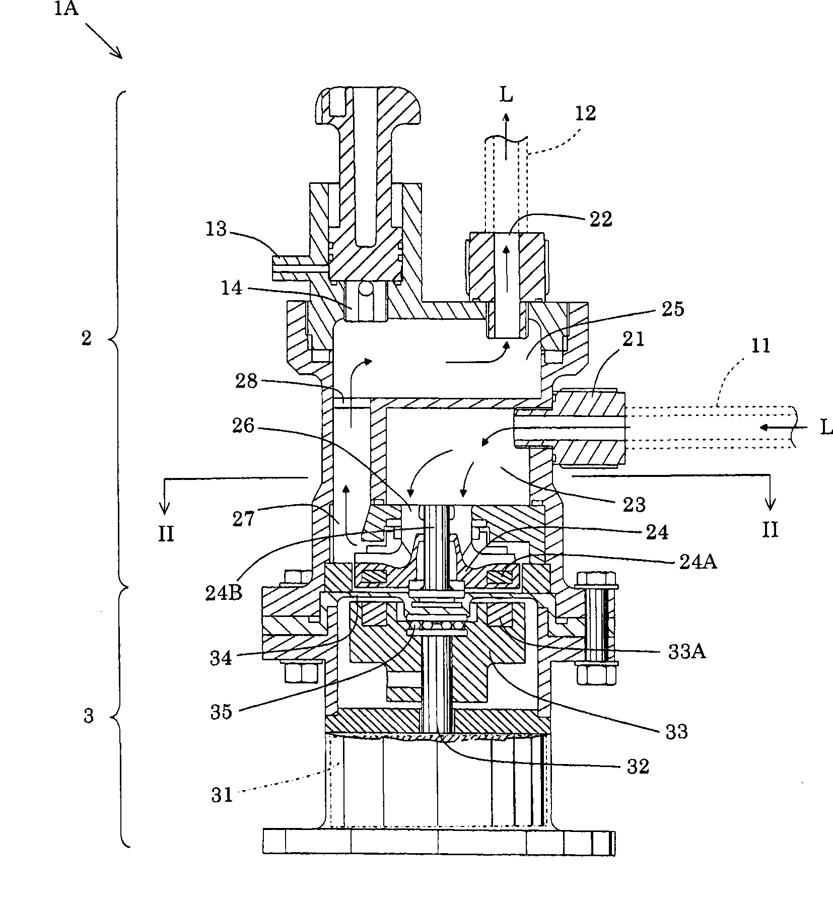
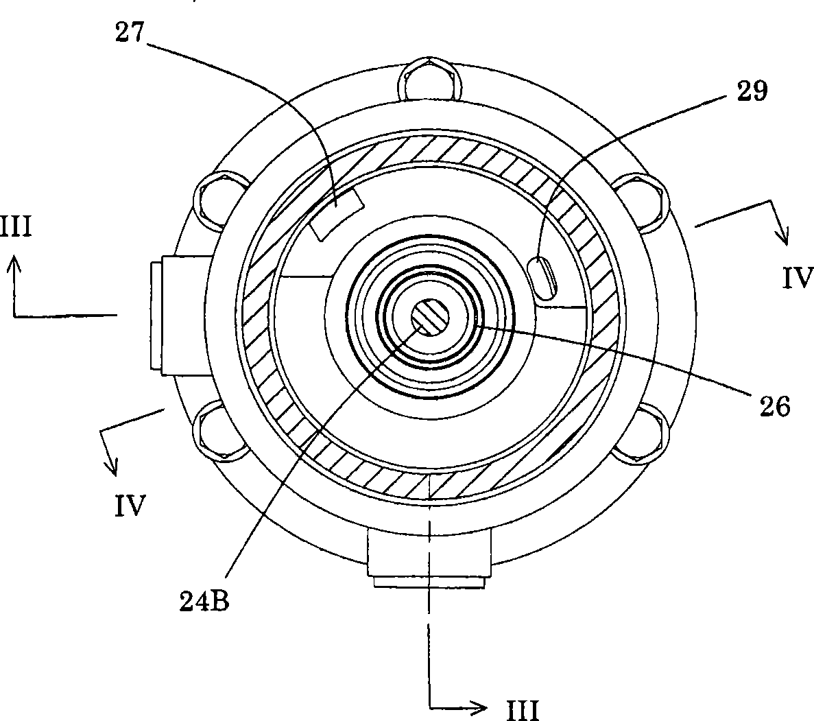
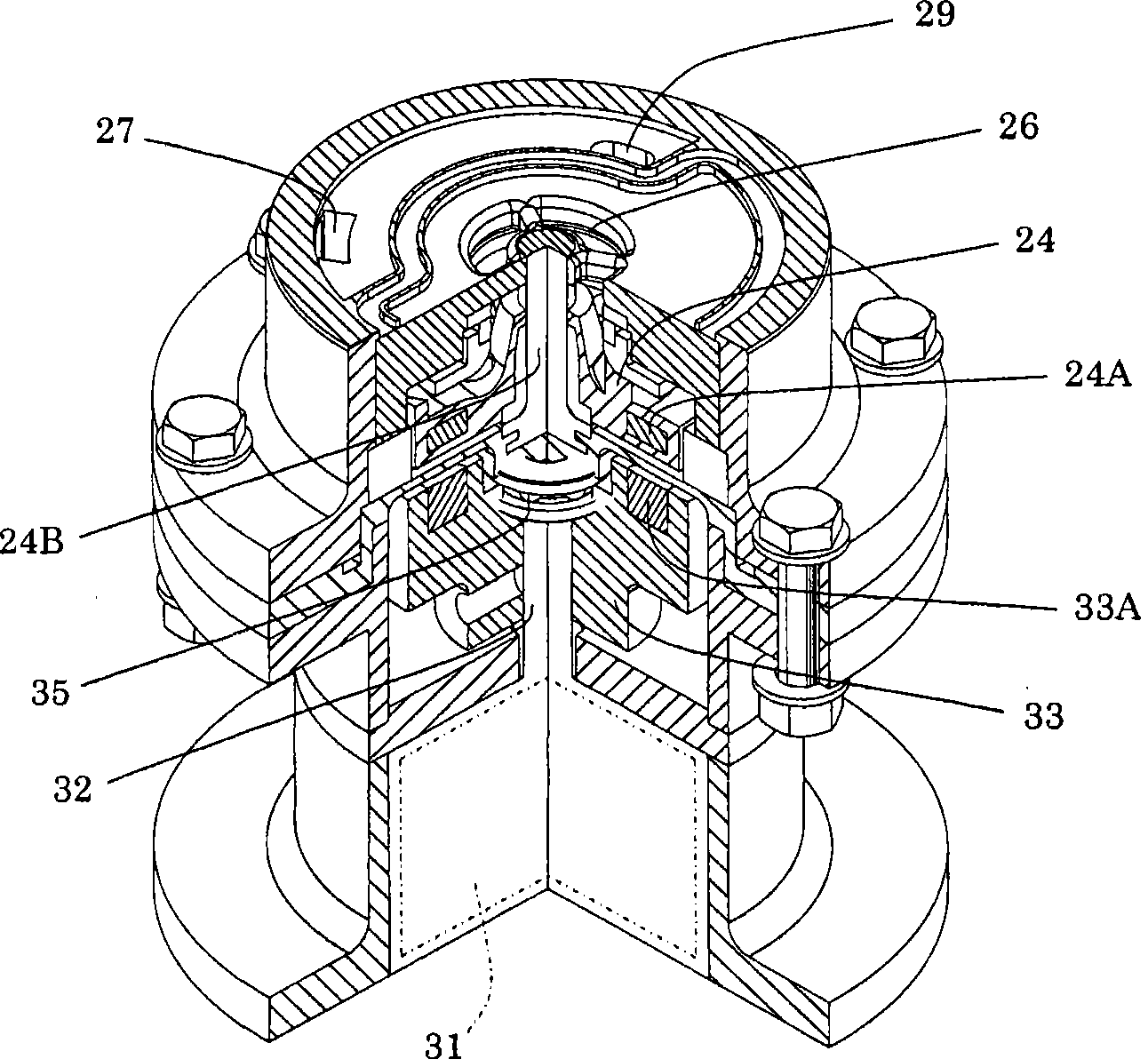
[0103] figure 1 It is a schematic sectional view showing an embodiment of a vertical self-priming pump according to the present invention, figure 2 Yes figure 1 A schematic enlarged cross-sectional view of the II-II line, image 3 is expressed in the ratio figure 1 In the structure of the lower part of the II-II line, in figure 2 A schematic enlarged cross-sectional view of the state where the III-III line is partially cut, Figure 4 is comparing figure 1 The II-II line is more of the lower part of the figure 2 A schematic enlarged cross-sectional view of line IV-IV, Figure 5 It is a schematic sectional view showing an embodiment of a vertical self-priming pump with a filter device according to the present invention, Image 6 Indicates the direction of liquid penetration relative to the filter Figure 5 The schematic enlarged end view of the VI-VI line. in additio...


PUM


Abstract

The subject of the invention is to provide a vertical self-suction pump which has low restriction in setting space and setting direction, and specifically provide a vertical self-suction pump which has easy and safe filter replacement operation, no requirement for pumping out the air in the pump or water injection before starting-up, and has low restriction in setting space and setting direction compared with the condition of adopting a horizontal pump structure, and is provided with a filtering device. The vertical self-suction pump adopts a valveless structure without a back valve. The vertical self-suction pump is characterized by comprising the following components: a pump part which is provided with a suction inlet, a suction chamber, an impeller, a self-suction chamber, a discharging opening in sequence from the upstream to the downstream of flow path, the suction inlet and the discharging opening are configured at positions above the suction chamber and the impeller, the self-suction chamber is configured at the position above the suction inlet and the discharging opening; and a driving part which is connected with the lower part of the pump body and becomes the driving source of pump body, wherein the rotation direction of impeller is an approximately horizontal direction.

Description

technical field [0001] The present invention relates to a vertical self-priming pump and a vertical self-priming pump with a filter device. self-priming pump. Background technique [0002] In the field of chemistry and other fields, filtration devices are generally used as means for removing impurities from various types of liquids. Among them, as a filter device equipped with a pump that sucks liquid stored in a container, etc., filters it with a filter, and then sends the liquid to a subsequent process, or returns to the aforementioned container for circulation, there are known devices equipped with There is a type of filter device with a push-in type back pressure valve (see Patent Documents 1 and 2, etc.). [0003] On the other hand, a self-priming chemical pump is known as a valveless self-priming pump (see Patent Document 3, etc.). [0004] In the filter devices of the forms of Patent Documents 1 and 2, when replacing the filter, it is necessary to extract the liqui...

Claims


Application Information

Patent Timeline
IPC IPC(8): F04D29/70F04D9/00F04D13/02
Inventor 森洋二芳贺康一
Owner WORLD CHEM CO LTD
Learn More