
Inclined shaft type hydraulic transformer and voltage transformation method

A technology of hydraulic transformers and inclined shafts, which is applied in the direction of physical quantity changers, machines/engines, liquid variable capacity machines, etc. It can solve the problems of loss of pressure transformation ability, reduction of pressure transformation efficiency, and increase of thrust, so as to expand the scope of use Effect

Inactive Publication Date: 2009-05-06
BAOTOU SAIBEI MECHANICAL EQUIP CO LTD
View PDF0 Cites 10 Cited by
  • Summary
  • Abstract
  • Description
  • Claims
  • Application Information

AI Technical Summary

Problems solved by technology

However, this change will also introduce another problem, that is, with the increase of the rotation angle of the valve plate, the matching angle of the notch between the rear end surface of the valve plate and the rear cover will continue to increase, so that the thrust on the rear end surface of the valve plate will continue to increase. increase, and then the supporting force continues to decrease, which eventually leads to an increase in internal leakage of the transformer, a decrease in transformation efficiency, and even loss of transformation capability
Therefore, this kind of hydraulic transformer has limited voltage transformation capability, which limits the application range of hydraulic transformers.

Method used


Image

  • Inclined shaft type hydraulic transformer and voltage transformation method
  • Inclined shaft type hydraulic transformer and voltage transformation method
  • Inclined shaft type hydraulic transformer and voltage transformation method

Examples


Embodiment Construction

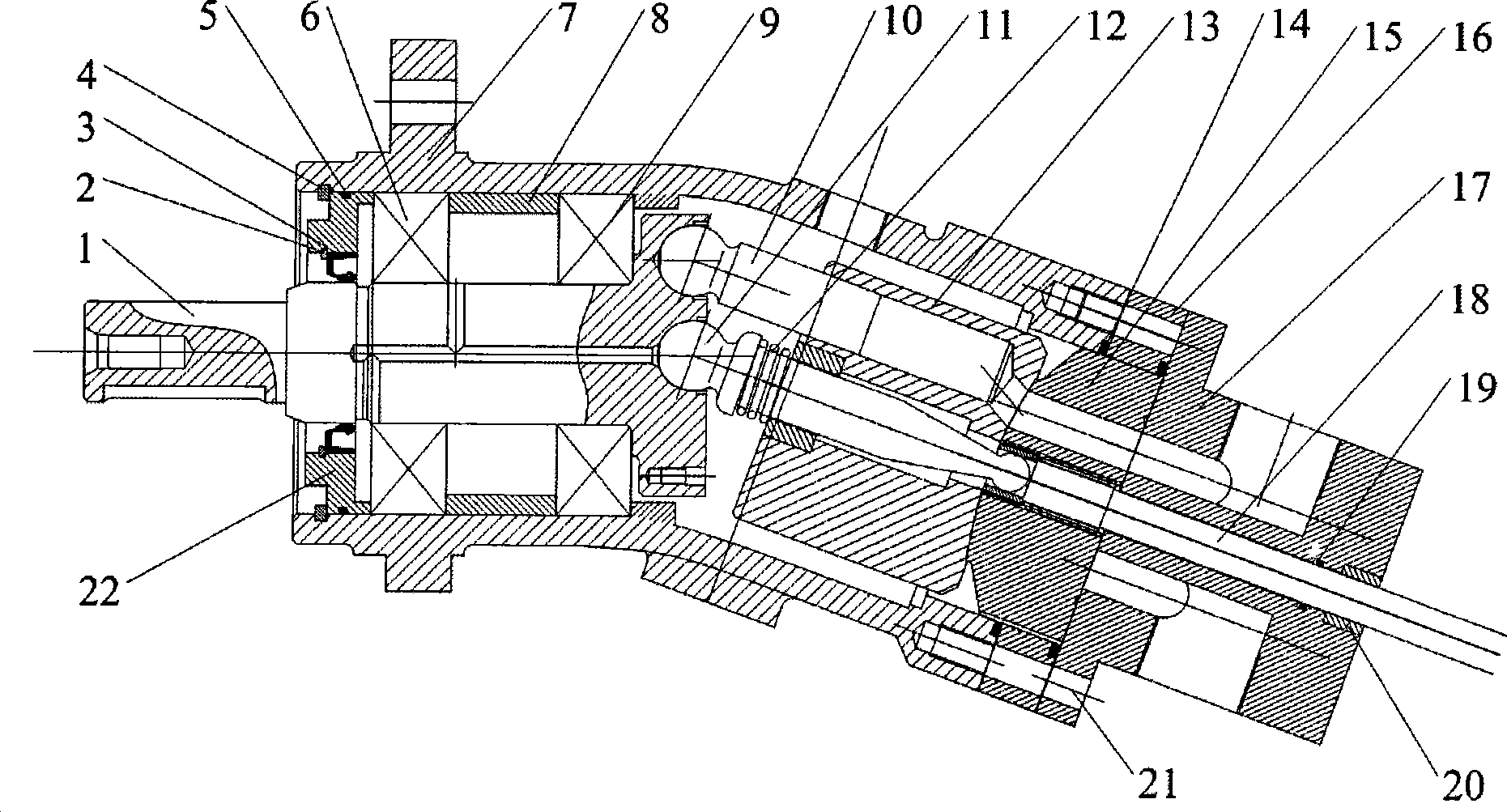
[0020] exist figure 1 Among them, a transition plate (16) is designed between the back cover (17) and the housing (7) of the hydraulic transformer, so that the thickness of the valve plate (15) can be increased, so that the valve plate (15) and the rotating rod (18) The spline connection between them can achieve sufficient strength. The rear end of the turning rod (18) can be connected with a rotary actuator or adjusted manually to control the input and output pressure and flow of the hydraulic transformer; parts (1-13) and parts (22) can be borrowed from the existing ramp Existing components for shaft pumps / motors.

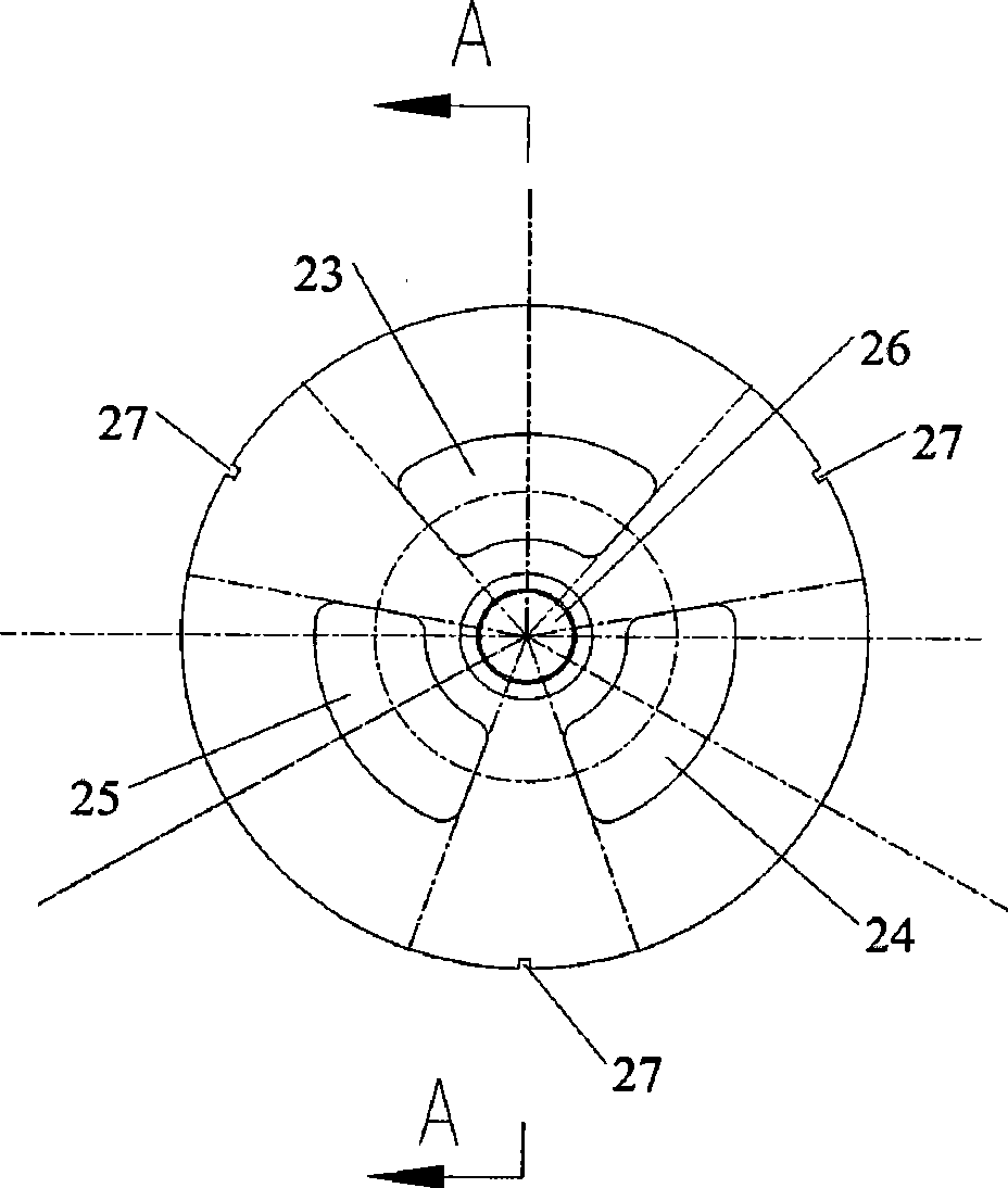
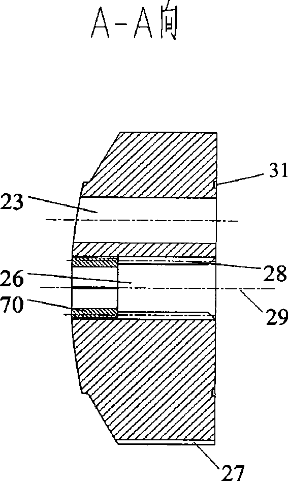
[0021] In Fig. 2, 3, 7, there are three distribution notches (23), (24), (25) evenly distributed on the distribution plate (15), used for input or output pressure oil; The center of the center is designed with a center hole (26), and the first half of the center hole (26) is pressed into the copper sleeve (70) for positioning with the ball head of the cylinder ...


PUM


Abstract

The invention relates to an oblique axle type hydraulic transformer. A hydraulic transformer reconstructed according to the prior oblique axle type hydraulic pump / motor is different to realize continuous voltage transformation of between 0 and 120 degrees under the condition of unchanging a structure of a shell. A transition plate is arranged between a rear cover and the shell; the rear end of a rotating rod is connected with an actuating mechanism or an angle is adjusted manually so as to achieve the aim of changing pressure. The invention puts forward a concept of using the transformation ratio of the hydraulic transformer by stages so as to fully utilize the function of voltage transformation which can be realized by the prior hydraulic transformer and utilize parts of mature elements of the hydraulic pump / motor.

Description

technical field [0001] The invention relates to a new type of hydraulic component, in particular to an inclined-axis hydraulic transformer capable of step-by-step voltage transformation. Background technique [0002] At present, the invention patents and utility model patents on hydraulic transformers are basically about how to overcome the defects of throttling during the voltage transformation process of hydraulic transformers, including the invention patents and utility model patents proposed by domestic and foreign universities such as Achten University and Zhejiang University in China. The new patent enables the hydraulic transformer to fully realize its variable voltage range from zero to positive infinity. [0003] The inventions of Achten University and Zhejiang University are mainly to change the distribution plate and the back cover of the hydraulic transformer. They have one thing in common, that is, the high pressure port is led to the center through the distribu...

Claims


Application Information

Patent Timeline
Patent Type & Authority Applications(China)
IPC IPC(8): F15B5/00F15B13/00F04B1/12
Inventor 胡纪滨苑士华魏超荆崇波李雪原彭增雄
Owner BAOTOU SAIBEI MECHANICAL EQUIP CO LTD
Learn More