Work vehicle

a technology for working vehicles and vehicles, applied in the field of work vehicles, can solve the problems of difficulty in keeping a sufficient space for disposing of exhaust gas processing devices, and achieve the effect of enhancing maintenance performance and improving performan

a technology for working vehicles and vehicles, applied in the field of work vehicles, can solve the problems of difficulty in keeping a sufficient space for disposing of exhaust gas processing devices, and achieve the effect of enhancing maintenance performance and improving performan

US20120247861A1Active Publication Date: 2012-10-04KOMATSU LTD

Image

  • Work vehicle
  • Work vehicle
  • Work vehicle

Examples


Embodiment Construction

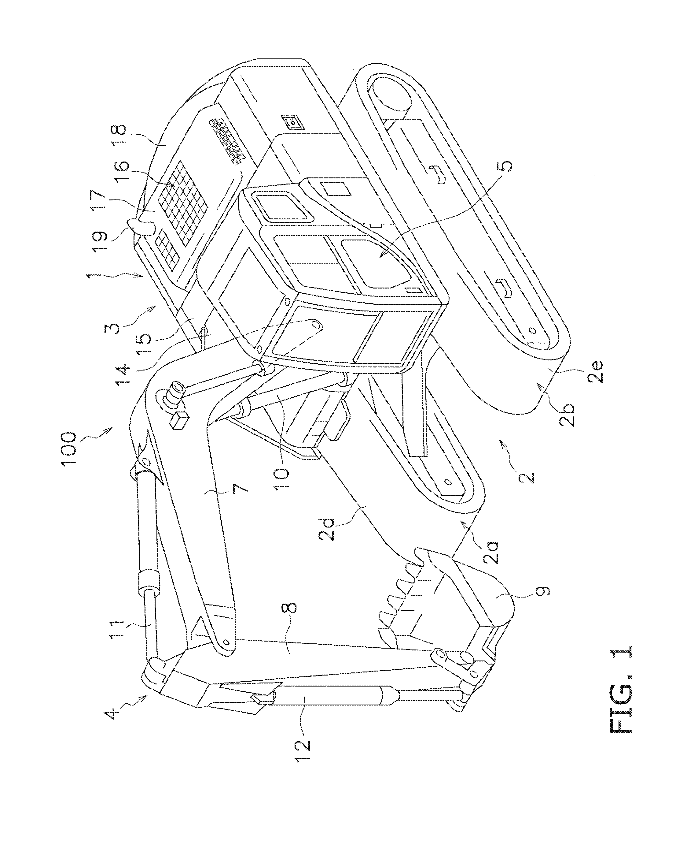
[0036]FIG. 1 illustrates a work vehicle 100 according to an exemplary embodiment of the present invention. The work vehicle 100 is a hydraulic excavator and includes a vehicle main body 1 and a working unit 4.

[0037]The vehicle main body 1 includes a travelling unit 2 and a revolving unit 3. The travelling unit 2 includes a pair of drive units 2a and 2b. The drive units 2a and 2b respectively have crawler belts 2d and 2e. The drive units 2a and 2b are configured to drive the crawler belts 2d and 2e by means of the driving force from an engine 21 to be described (see FIG. 2) for causing the work vehicle 100 to travel. It should be noted in the following explanation that “a back-and-forth direction” refers to the longitudinal direction of the vehicle main body 1. Further, “a right-and-left direction” or “a lateral / sideward direction” refers to a transverse / vehicle-width direction.

[0038]The revolving unit 3 is mounted on the travelling unit 2. The revolving unit 3 is revolvable with res...


PUM


Abstract

In a work vehicle, a second processing device, disposed over a hydraulic pump, is configured to process the hydraulic gas from an engine. A first processing device is disposed closer to the engine than the second processing device is Further, the first processing device is positioned higher the second processing device. The first processing device is partially overlapped with the second processing device in a top plan view.

Description

CROSS-REFERENCE TO RELATED APPLICATIONS[0001]This application claims priority to Japanese Patent Application No. 2010-124903 filed on May 31, 2010, the disclosure of which is hereby incorporated herein by reference in its entirety.TEHHNICAL FIELD[0002]The present invention relates to a work vehicle.BACKGROUND ART[0003]Work vehicles are embedded with an exhaust gas processing device. For example, the exhaust gas processing device is a device configured to reduce nitrogen oxides (NOx), a device configured to reduce carbon monoxide (CO), a device configured to reduce particulate substances or etc. The exhaust gas processing device is connected to an engine through a pipe for processing the exhaust gas from the engine. Therefore, the exhaust gas processing device is accommodated in the inside of a work vehicle together with the engine. Further, as described in Japanese Laid-open Patent Application Publication No. JP-A-2008-156835, some work vehicles are embedded with a plurality of exha...

Claims


Application Information

Patent Timeline
04 Oct 2012
Publication
US20120247861A1
IPC
B60K13/04; F01N3/035
CPC
B60K13/04; B60Y2200/412; E02F9/0866; Y02T10/20; F01N13/1805; F01N2590/08; F01N3/00; Y02T10/12
Inventors
MIZUNO, HIROYUKI; UEDA, TOMOMI