Diffusing plate and diffusing plate group

A technology of diffuser plate and pattern, applied in diffuser elements, nonlinear optics, instruments, etc., can solve problems such as insufficient diffusion and achieve the effect of best display quality

Active Publication Date: 2009-05-06
ENTIRE TECH CO LTD
View PDF0 Cites 7 Cited by
  • Summary
  • Abstract
  • Description
  • Claims
  • Application Information

AI Technical Summary

Problems solved by technology

Therefore, there will still be the

Method used


Image

  • Diffusing plate and diffusing plate group
  • Diffusing plate and diffusing plate group
  • Diffusing plate and diffusing plate group

Examples


Embodiment Construction

[0028] The above and other technical features and advantages of the present invention will be described in more detail below in conjunction with the accompanying drawings.

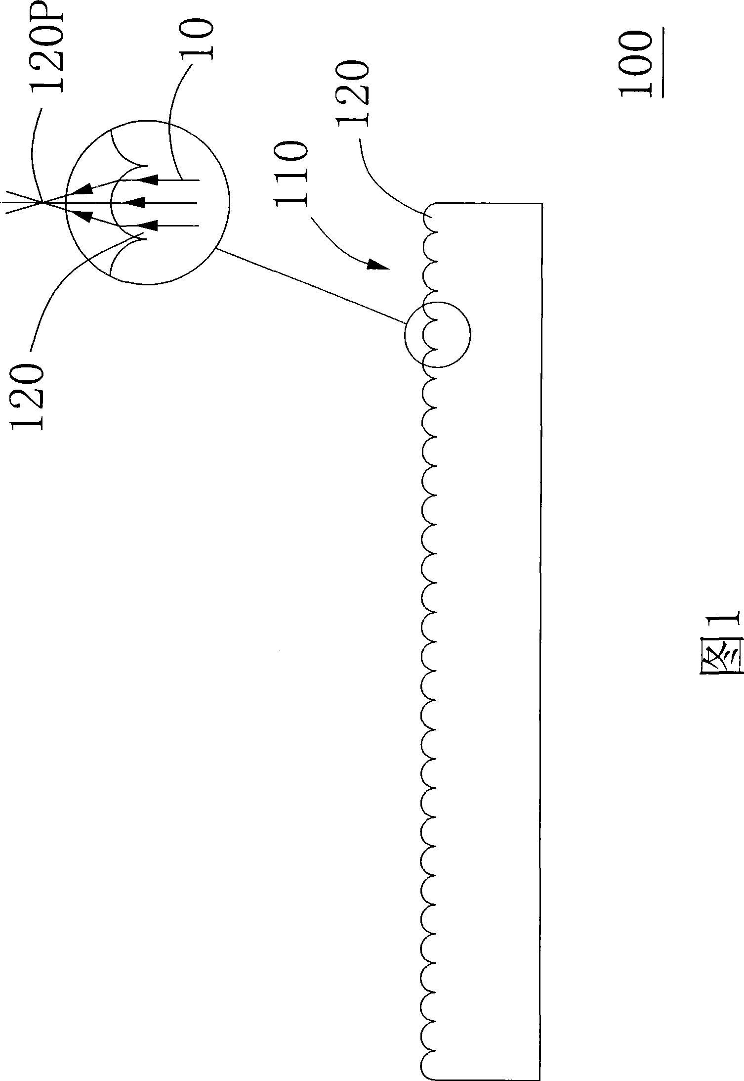
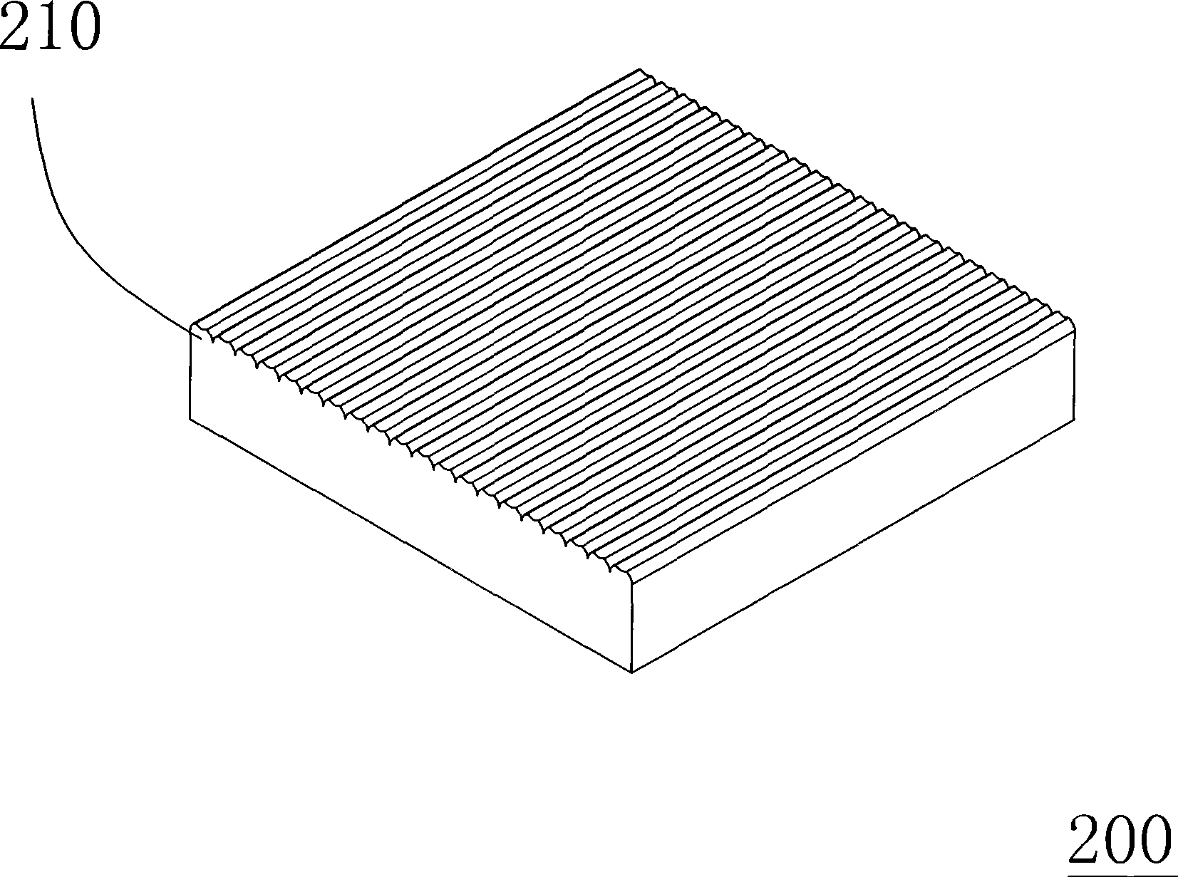
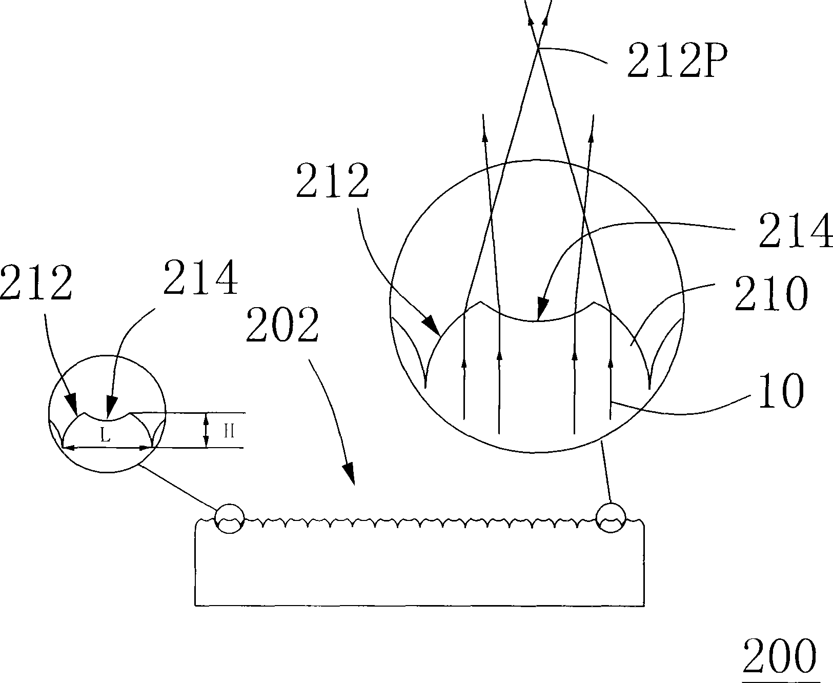
[0029] see Figure 2A and Figure 2B , Figure 2A Shown is a perspective view of the diffuser plate of the first embodiment of the present invention, Figure 2B Shown is a side view of the diffuser plate of the first embodiment. The light emitting surface 202 of the diffuser plate 200 has a plurality of strip-shaped patterns 210, the patterns 210 are structures protruding outward, and the longitudinal length H of the patterns 210 is less than half of the lateral width L . Please refer to Figure 2B ,Depend on Figure 2B It can be seen that the outline of the pattern 210 has a first arc 212 and a second arc 214, and the protruding directions of the first arc 212 and the second arc 214 are opposite to each other, that is, the first arc 212 is toward the diffuser plate The outside of the diffusion plate ...


PUM

PropertyMeasurementUnit
Top angleaaaaaaaaaa

Abstract

The invention relates to a diffusing plate which is mainly formed by light-transmitting materials. The light reflecting surface of the diffusing plate is provided with a plurality of long strip-shaped patterns, the outline of each pattern is provided with a first arc shape and a second arc shape, the convex directions of the first arc shape and the second arc shape are mutually opposite, wherein the second arc shape is an arc, and the curvature radius of the second arc shape is from 0.05 mm to 0.3 mm.

Description

technical field [0001] The present invention relates to a diffuser plate and a diffuser plate set, in particular to a diffuser plate with a plurality of strip-shaped patterns on the light-emitting surface and a diffuser plate set with the diffuser plate. Background technique [0002] In recent years, traditional cathode ray tube displays (commonly known as CRT displays) have been gradually replaced by liquid crystal displays. The main reason is that the amount of radiation emitted by liquid crystal displays is much smaller than that of CRT displays. Manufacturing costs are also significantly reduced. Generally speaking, a liquid crystal display includes a backlight module and a liquid crystal panel. The main function of the backlight module is to provide a light source for the liquid crystal display. [0003] Generally speaking, a backlight module usually includes a diffuser plate, which is mainly composed of a polymer light-transmitting material doped with a plurality of l...

Claims


Application Information

Patent Timeline
IPC IPC(8): G02B5/02G02F1/13357G02F1/1335
Inventor 杨宗长郑文峰
Owner ENTIRE TECH CO LTD
Why Eureka
Try Eureka