
LCD device

A technology of liquid crystal display device and black matrix layer, which is applied to optics, instruments, electrical components, etc., can solve problems such as increased manufacturing cost, display quality problems, contact with vertical DC bias electric field, etc., so as to improve quality, reduce engineering costs, The effect of removing afterimages

Inactive Publication Date: 2009-05-06
SHANGHAI SVA LIQUID CRYSTAL DISPLAY
View PDF0 Cites 29 Cited by
  • Summary
  • Abstract
  • Description
  • Claims
  • Application Information

AI Technical Summary

Problems solved by technology

The use of liquid crystal doping technology, on the one hand, increases the manufacturing cost, and on the other hand, it will bring display quality problems such as dotted mura when the liquid crystal is dripped
These two existing methods for the vertical DC bias electric field cannot fundamentally touch the vertical DC bias electric field

Method used


Image

  • LCD device
  • LCD device
  • LCD device

Examples


Embodiment Construction

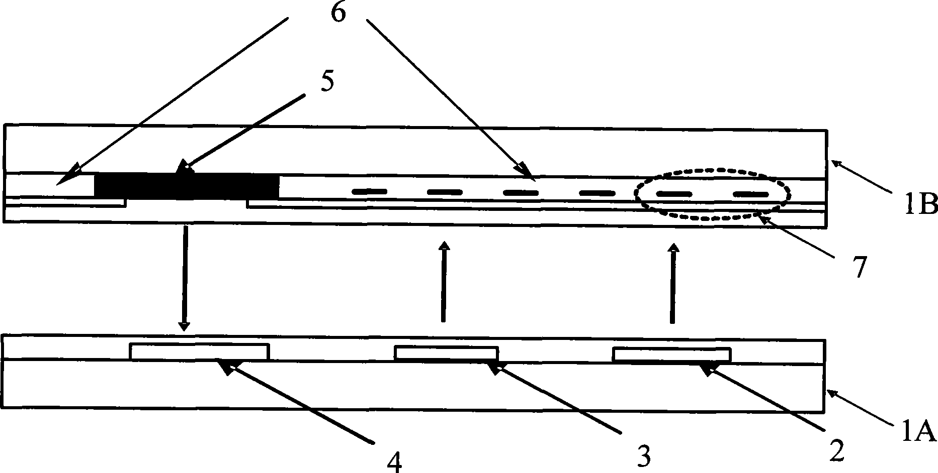
[0021] The liquid crystal display device of the present invention will be further described in detail with reference to the accompanying drawings.

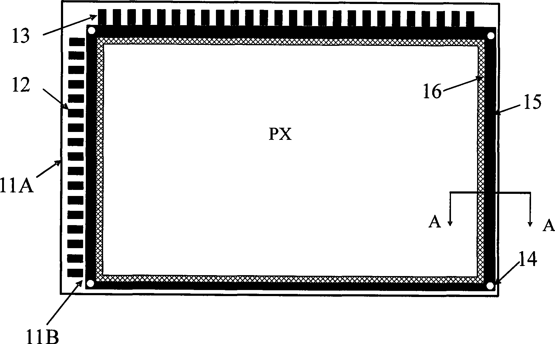
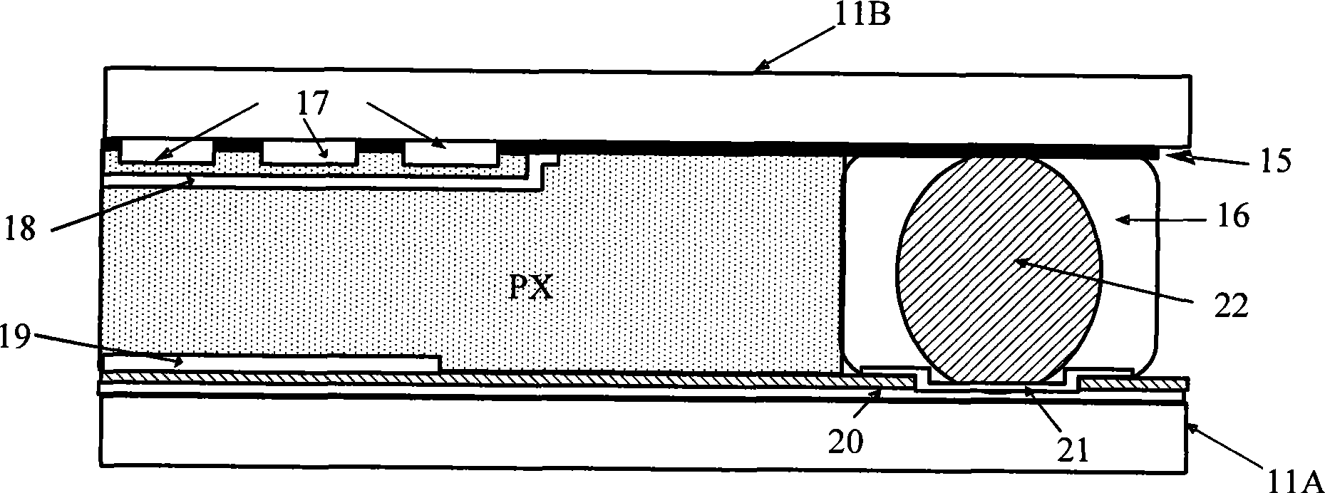
[0022] figure 2 It is a plan view of the first embodiment of the liquid crystal display device of the present invention. Such as figure 2 As shown, the liquid crystal display device is a transverse electric field type liquid crystal display device, which includes an array substrate 11A and a color filter substrate 11B, and the sealing glue 16 is used to connect the array substrate 11A and the color filter substrate 11B. One side of the array substrate 11A includes signal line terminals 13 , scan line terminals 12 , a display area PX, a peripheral portion of the display area, and an alignment film covering the display area. There are also coordination holes to which transfer electrodes 14 are connected at the four corners of this display device. One side of the color filter substrate 11B includes a display area and a periphera...


PUM


Abstract

The invention relates to a liquid crystal display device which comprises an array base plate, a colored filter base plate arranged relatively to the array base plate, a metal layer with an earth potential, and a black matrix layer positioned at one side of the colored filter base plate, wherein the array base plate and the colored filter base plate are connected by a sealant; the metal layer with an earth potential is distributed at one side of the array base plate and a conducting layer is formed on the metal layer with an earth potential; and a conducting component is formed between the conducting layer and the black matrix layer and is connected with the conducting layer and the black matrix layer. The liquid crystal display device can prevent an opening part from forming a longitudinal direct current biasing electric field and ensure enough and stable earth potential on a black matrix, thereby eliminating an afterimage in an image and improving the quality of the liquid crystal display device.

Description

technical field [0001] The invention relates to a liquid crystal display device, in particular to a liquid crystal display device capable of eliminating afterimages. Background technique [0002] Thin film transistor liquid crystal display devices have gradually occupied the vast majority of the display market due to their advantages of thinness, lightness, power saving, and environmental protection. With the popularization of liquid crystal display devices, the performance requirements for liquid crystal display devices are gradually increasing, such as high brightness, high contrast, wide viewing angle, high chromaticity range, high response speed and so on. In addition, people have higher and higher requirements on image quality of liquid crystal display devices such as mura and afterimage. [0003] Afterimage is a very significant defect that exists after the size of the liquid crystal display device is enlarged, especially in the lateral electric field type liquid crys...

Claims


Application Information

Patent Timeline
Patent Type & Authority Applications(China)
IPC IPC(8): G02F1/1362G02F1/1339G02F1/1335H01L27/12H01L21/77
Inventor 马群刚
Owner SHANGHAI SVA LIQUID CRYSTAL DISPLAY
Learn More