Fluid generator

A generator and fluid technology, which is applied to synchronous motors with rotating armatures and stationary magnets, electrical components, electromechanical devices, etc., can solve the problem of large resistance, uncompact structure of fluid power generation devices, and difficulty in facilitating multiple fluid generators. Parallel power generation and other issues to achieve the effect of compact structure

Inactive Publication Date: 2009-05-06
冯岩
View PDF0 Cites 5 Cited by
  • Summary
  • Abstract
  • Description
  • Claims
  • Application Information

AI Technical Summary

Problems solved by technology

[0003] The purpose of the present invention is to design and manufacture a fluid generator to overcome the uncompact structure of the current fluid power generators, especially when multiple fluid generators are to be used for parallel power generation, the structure is complicated and the resistance is large, and it is difficult to conveniently realize multiple Disadvantages of fluid generators for parallel power generation in order to better utilize the energy of various fluids, especially low potential energy fluids

Method used


Image

  • Fluid generator
  • Fluid generator
  • Fluid generator

Examples


Embodiment Construction

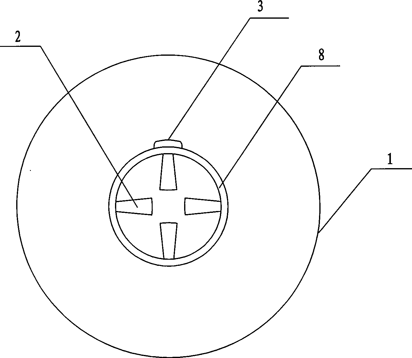
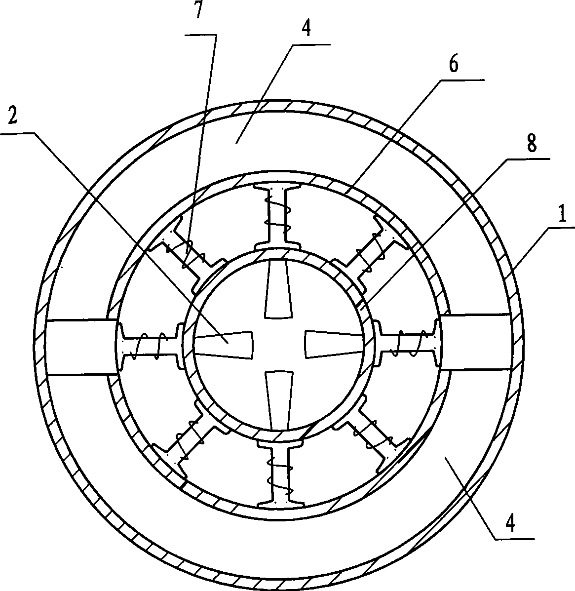
[0010] In the present invention, a plurality of single generators are installed in the outer cylinder body 1 . Every single fluid generator has a stator 4 fixed on the inner wall of the outer cylinder 1, a shaft sleeve 6 placed between the stator 4 and the rotor 7, a rotor 7 fixed on the outer wall of the inner cylinder 8 that can rotate on the inner wall of the shaft sleeve 6, and the outer wall is fixed with The rotor 7 has an inner cylinder 8 with multiple blades 2 fixed on its inner wall, and multiple blades 2 fixed on the inner wall of the inner cylinder 8 . A plurality of single fluid generators are evenly spaced on the inner wall of the outer cylindrical body 1 .

[0011] Provide the embodiment of the two-pole direct-current fluid generator that uses permanent magnet material as stator 4 below.

[0012] attached figure 1 A front view of an embodiment of the invention is given. The outer cylinder body 1 is made of a non-magnetic metal plate, and the electric brush 3 i...


PUM


Abstract

The invention relates to a fluid electric generator which comprises an outer tube body, the outer tube body is provided with a plurality of single fluid electric generators, the single fluid electric generators comprise a stator, an axle sleeve, a rotor, an inner tube and a plurality of blades. The invention integrates the fluid energy collector and the electric generator into a whole, has compact structure, can facilitate the parallel electric generation of the fluid electric generators, and can better utilize the energy of various fluids, especially of the low level energy fluids.

Description

1. Technical field [0001] The invention belongs to the technical field of electromechanical engineering, and in particular relates to the design and manufacture of fluid generators. 2. Background technology [0002] The current fluid power generation device generally has an independent impeller for collecting energy, and a generator whose central shaft is connected to the energy output shaft of the impeller. The structure of the generator is to adopt a rotor with windings fixed on the central Electricity is generated in the form of induced electromotive force by rotating in a magnetic field. The fluid power generation device based on the above structure is not compact in structure, especially when it is necessary to realize parallel power generation of multiple fluid power generators, the structure is complicated and the resistance is large, and it is difficult to conveniently realize multiple fluid power generators for parallel power generation, so as to better Utilize the...

Claims


Application Information

Patent Timeline
Patent Type & Authority Applications(China)
IPC IPC(8): H02K7/18H02K21/28H02K1/22
Inventor 冯岩
Owner 冯岩
Why Eureka
Try Eureka