Multi-level rectifying T type converter topology structure

A technology of multi-level rectification and topology structure, which is applied in the direction of converting AC power input to DC power output, output power conversion devices, electrical components, etc. Balance, multi-level restrictions and other issues, to achieve the effect of reducing the number, high-level solutions, and good scalability

Inactive Publication Date: 2009-05-06
BEIJING JIAOTONG UNIV
View PDF0 Cites 12 Cited by
  • Summary
  • Abstract
  • Description
  • Claims
  • Application Information

AI Technical Summary

Problems solved by technology

[0002] Two-level converter circuits are widely used in various fields such as railways and industries. However, in high-voltage applications, the two-level converter must be connected to the high-voltage power grid through a transformer due to the limitation of the withstand voltage of the device. The power frequency transformer greatly increases the cost and volume of the power electronic conversion device
[0003] At present, in the topology of the existing multilevel converter, as the number of levels increases, the number of semiconductor devices required increases sharply; as the number of levels increases, it is not easy to balance the voltages of each capacitor. The common problems in the multi-level structure make the multi-level have certain limitations in practical use

Method used


Image

  • Multi-level rectifying T type converter topology structure
  • Multi-level rectifying T type converter topology structure
  • Multi-level rectifying T type converter topology structure

Examples


Embodiment Construction

[0018] The present invention will be further described in conjunction with accompanying drawing:

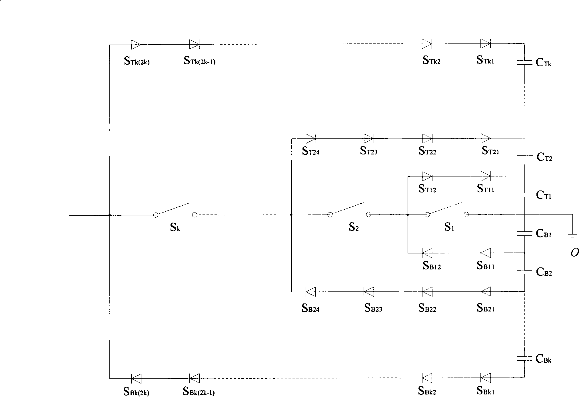
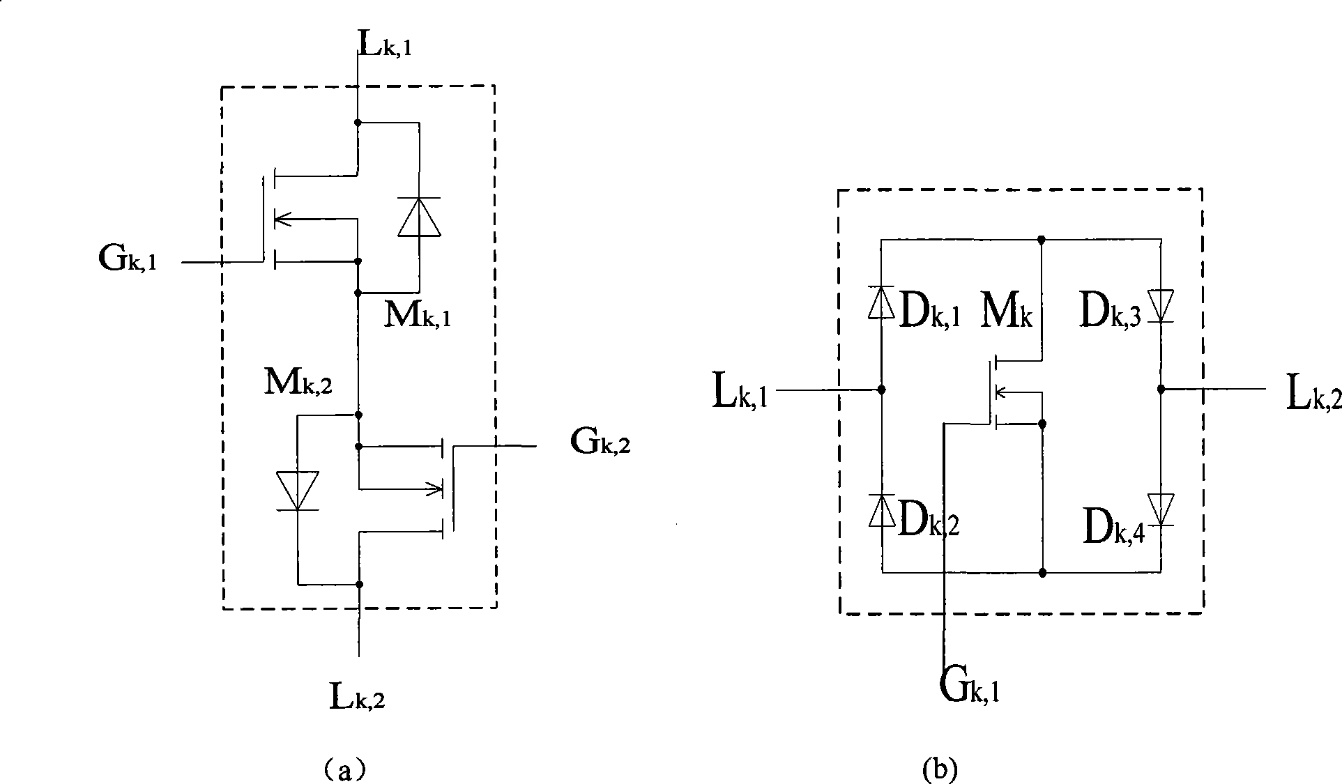
[0019] figure 1 Circuit schematic diagram for a single bridge arm, through C T1 、C T2 ...C Tk-1 、C Tk , C B1 、C B2 ...C Bk-1 、C Bk A total of 2k capacitors constitute the vertical axis of the T-type converter; through S 1 , S 2 ... S k-1 , S k A total of k bidirectional controllable switches constitute the transverse axis of the T-type converter, and the bidirectional controllable switch can be realized by two IGBTs in reverse series or other semiconductor devices capable of realizing bidirectional switching functions and their topological circuits.

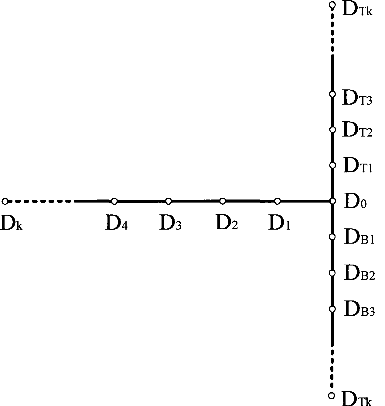
[0020] bi-directional switch S i , S i+1 Node D between (i=1, 2...k-1) i and capacitance C Ti 、C Ti+1 Node D between (i=1, 2...k-1) Ti between is controlled by the unidirectional switch S Tk1 , S Tk2 ... S Tk(2k) Constitute a one-way rectification branch flowing from the horizontal axis to the vertical axis, at n...


PUM


Abstract

The invention discloses a topology structure of a multi-level T-shaped converter for realizing rectification conversion, which is characterized in that the longitudinal axle of the T-shaped converter is formed by capacitors CT1, CT2 to CTk-1, CTk, CB1, CB2 to CBk-1 and CBk (2k capacitors in all); the horizontal axle of the T-shaped converter is formed by S1, S2 to Sk-1 and Sk two-way controllable switches (k in all); a branch circuit is arranged between a node Di between an Si and an Si+1 (i equals to1,2 to k-1) and a node DTi between a CTi and a CTi+1 (I equals to 1,2 to k-1), a one-way rectification branch circuit flowing to the longitudinal axle from the horizontal axle is formed via an STk1, an STk2 to STk(2k), the other branch circuit is arranged between a node Di and a node DBi between a CBi and a CBi+1 (i equals to 1,2 to k-1), the branch is a one-way rectification branch circuit flowing to the horizontal axle from the longitudinal axle and is formed by an SBk1, an SBk2 to SBk(2k), and the direction is opposite to the direction of the branch circuit; one end of the two-way controllable switch S1 of the horizontal axle is connected with the center points of the capacitors of the longitudinal axle. A switching tube, the capacitors and the rectification branch circuits are extended to increase the level number; and the invention can be applied to a multi-phase system by single-phase circuit combination. The invention can easily increase the level number of the converter and overcome the defects of non-uniform voltage of the capacitors and the large number of the parts of the prior proposal.

Description

technical field [0001] The invention relates to a topological structure of a rectification circuit, in particular to a topological structure of a multilevel converter capable of realizing rectification. Background technique [0002] Two-level converter circuits are widely used in various fields such as railways and industries. However, in high-voltage applications, the two-level converter must be connected to the high-voltage power grid through a transformer due to the limitation of the withstand voltage of the device. The power frequency transformer greatly increases the cost and volume of the power electronic conversion device. [0003] At present, in the topology of the existing multilevel converter, as the number of levels increases, the number of semiconductor devices required increases sharply; as the number of levels increases, it is not easy to balance the voltages of each capacitor. The common problems in the multi-level structure make the multi-level have certain ...

Claims


Application Information

Patent Timeline
Patent Type & Authority Applications(China)
IPC IPC(8): H02M7/217
Inventor 郑琼林贺明智游小杰林飞孙湖黄先进张立伟
Owner BEIJING JIAOTONG UNIV
Why Eureka
Try Eureka