Cylindrical member maintenance device

A maintenance equipment, cylindrical technology, used in bridge parts, bridge construction, cleaning methods using liquids, etc., can solve problems such as inability to clean the depths of adjacent strand grooves, wire brush wear, etc.

Inactive Publication Date: 2009-05-06
H & H ENG
View PDF2 Cites 29 Cited by
  • Summary
  • Abstract
  • Description
  • Claims
  • Application Information

AI Technical Summary

Problems solved by technology

Prior art cable cleaners clean the ridges of the cable, i.e. the outermost parts of the strands, but do not clean deep inside the grooves between

Method used


Image

  • Cylindrical member maintenance device
  • Cylindrical member maintenance device
  • Cylindrical member maintenance device

Examples


Embodiment Construction

[0043] figure 1 :

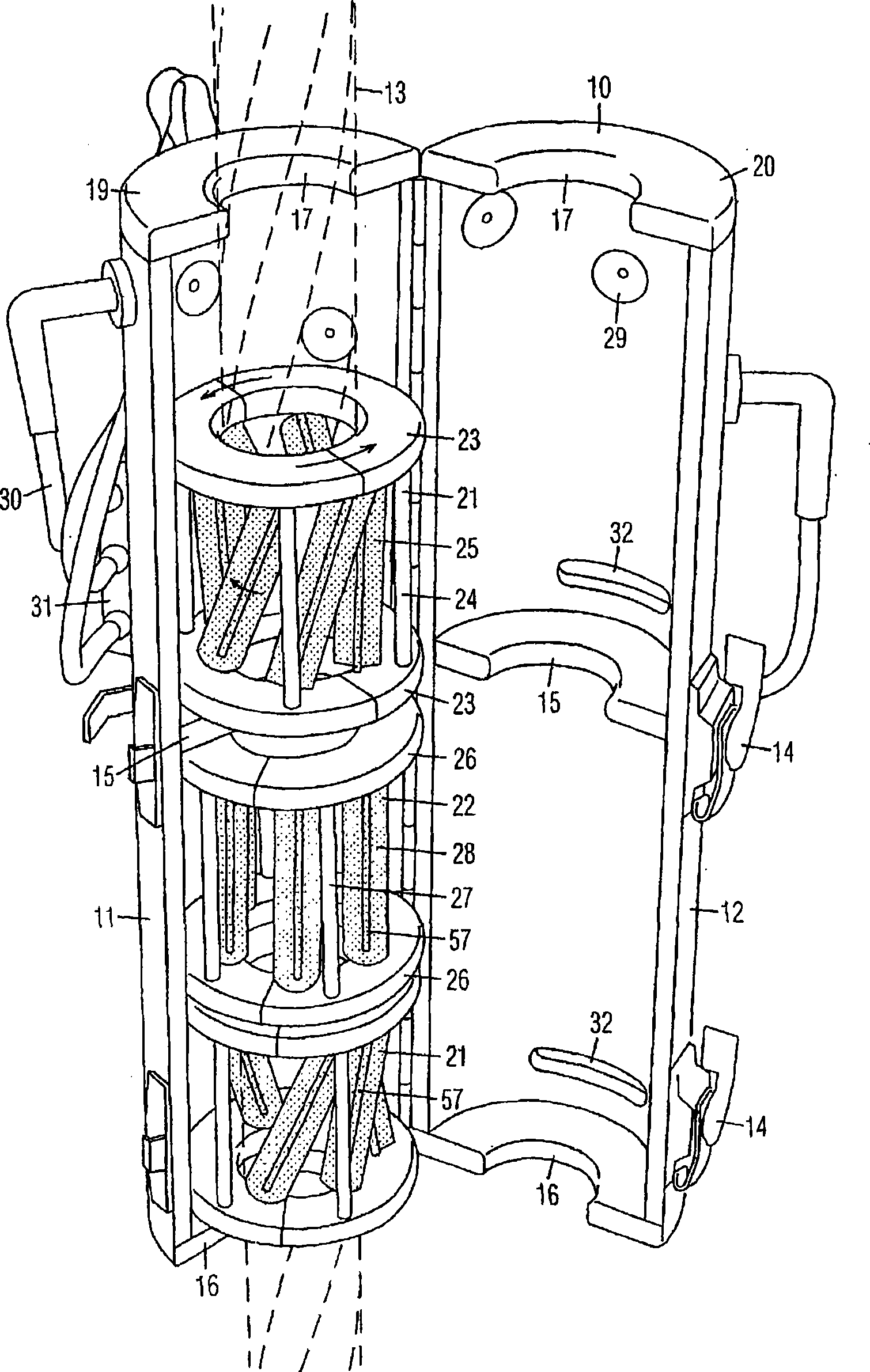
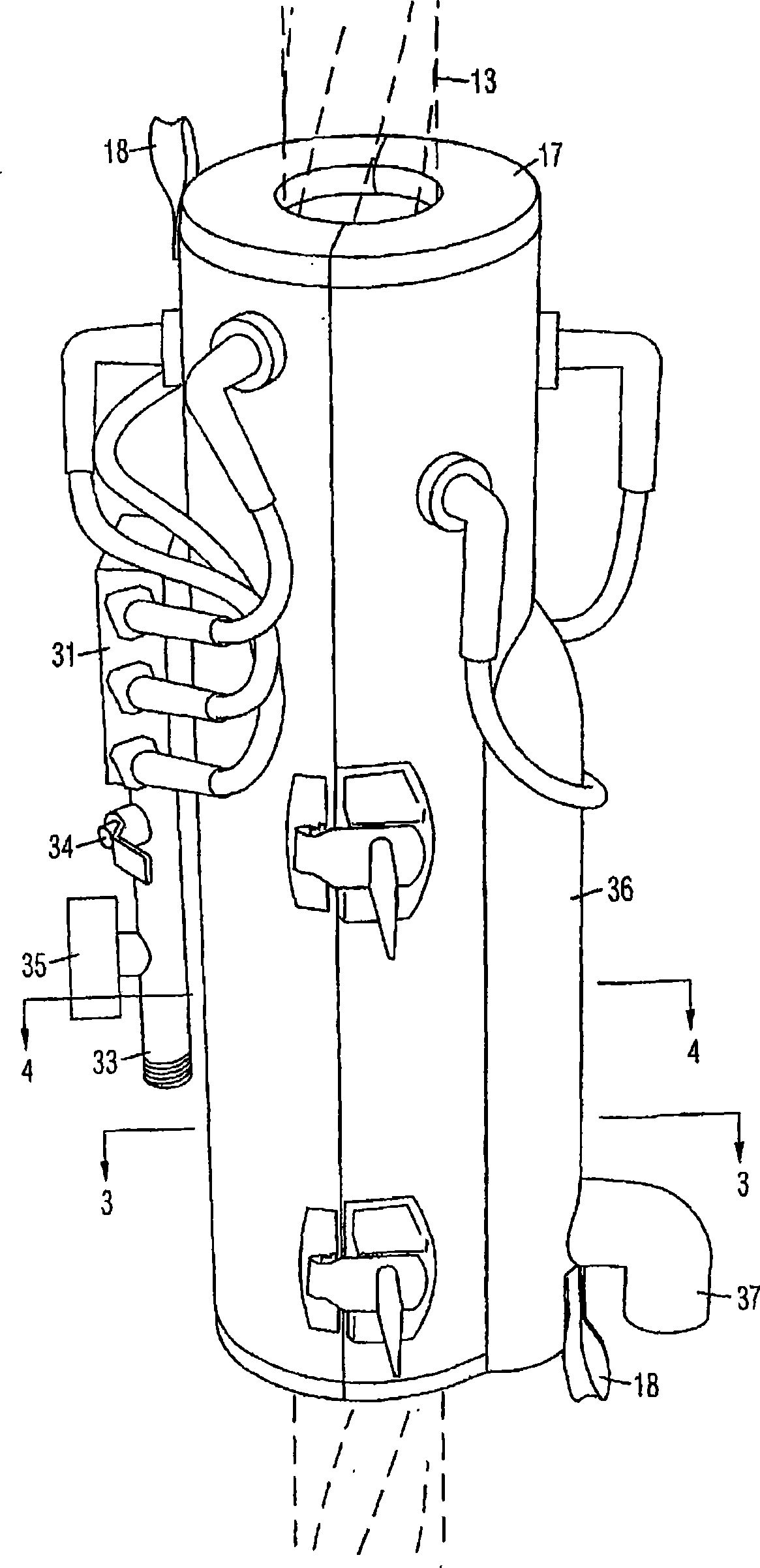
[0044] The cylindrical member maintenance equipment in the open position is in the figure 1 Shown in perspective view. It comprises a housing 10 comprising two hinged housing halves 11 and 12 to close around a cylindrical member 13, such as a braided steel cable. The cleaner can be used to clean other types of cylindrical components, such as pipes. The housing halves 11 and 12 are locked together by a latch 14 after closing around the cylindrical member 13 .

[0045] Split alignment rings 15 and 16 in the housing align cylindrical member 13 therein and seal the interior of housing 10 from the external environment. A split seal ring 17 is located at the first end of the housing 10 . The sealing ring 17 has a slightly larger inner diameter than the inner diameters of the alignment rings 15 and 16 to avoid touching the cylindrical member 13 . The rings 15 - 17 each comprise two half rings 19 and 20 attached to respective housing halves 11 and 12 so that ...


PUM


Abstract

A cylindrical member maintenance device is comprised of a housing (10) comprised of two hinged halves (11, 12) for being closed around a cylindrical member (13), such as a stranded steel cable. A rotary helical brush assembly (21) and a rotary longitudinal brush assembly (22) are positioned in the housing and rotatable about an axis of the housing. Each rotary brush assembly is comprised of coaxial split rings (23, 26) with rotary cylindrical wire brushes (25, 28) connected in between and which are independently rotatable about their own axes. Nozzles (29) are positioned on the inside of the housing for applying a cleaning fluid or paint to the cylindrical member. Apertures (32) in the housing are for connecting to a suction device for removing debris, cleaning fluid, and paint to avoid contaminating the environment. Loops (18) on the housing are for attaching to cables for moving the housing along the cylindrical member.

Description

technical field [0001] The present invention relates broadly to apparatus for cleaning structural cables and other cylindrical members. Background technique [0002] Braided steel cables, such as the type used on suspension bridges, comprise a plurality of braided strands wound helically around a solid core. The cables are made of steel and thus require periodic maintenance to prevent rusting. This maintenance involves removing surface dirt, rust, and old paint, and then applying the cleaned surface. [0003] Typical cleaning equipment for cleaning braided steel cables includes a housing that positions wire brushes around the cables. The cable is cleaned by said wire brushes as the cleaning device moves along the cable. Some cleaning devices use a cleaning fluid. Prior art cable cleaners clean the lands of the cable, ie the outermost parts of the strands, but cannot clean deep inside the grooves between adjacent strands. Wire brushes also wear out quickly. Additionally...

Claims


Application Information

Patent Timeline
IPC IPC(8): B08B9/023B08B1/02B08B1/04B08B3/02
CPCB08B1/02B08B3/024E01D19/16B08B1/04B05B13/0207E01D19/106B08B3/022B08B9/023B08B1/008
Inventor 史蒂文·A·休曼理查德·D·霍华德
Owner H & H ENG
Why Eureka
Try Eureka