A method of storing energy and a cryogenic energy storage system

An energy storage system and energy storage technology, applied in the field of energy storage and low-temperature energy storage systems, can solve problems such as expensive, radiation risk, and nuclear waste pollution

Active Publication Date: 2009-05-06
HIGHVIEW ENTERPRISES LTD
View PDF0 Cites 18 Cited by
  • Summary
  • Abstract
  • Description
  • Claims
  • Application Information

AI Technical Summary

Problems solved by technology

Nuclear power systems not only produce nuclear waste pollution but also have radiation

Method used


Image

  • A method of storing energy and a cryogenic energy storage system
  • A method of storing energy and a cryogenic energy storage system
  • A method of storing energy and a cryogenic energy storage system

Examples


Embodiment Construction

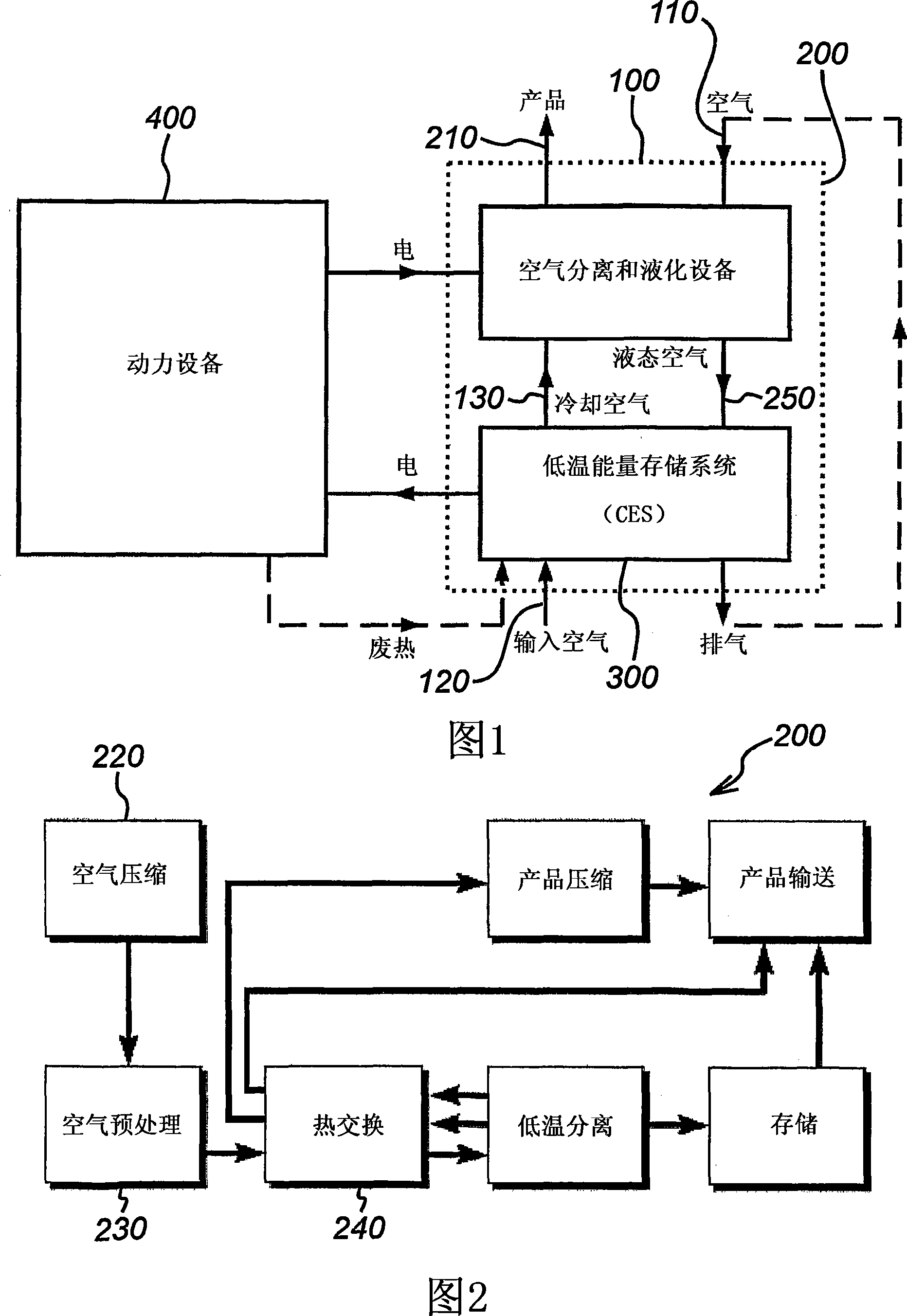
[0110] A conceptual design of the energy storage system of the present invention is shown in FIG. 1 . The entire system is shown within dashed box 100 . The system 100 consists of two main parts: the air liquefaction part 200 and the cryogenic energy storage unit (CES) 300 . During off-peak hours, excess electricity is supplied to the air liquefaction plant 200 to produce liquid air, which is then used to generate electricity through the CES 300 during peak hours. The power plant 400 and the entire energy storage system 100 only have to exchange electricity, so no changes to the power plant 400 are required, thereby ensuring maximum adaptability. At the same time, the CES 300 can use any available waste heat from the exhaust of the power plant 400 to heat the working fluid.

[0111] Within the energy storage system 100, there are two main air flows. A stream 110 supplies air to the air liquefaction plant 200 to liquefy the air and store it as liquid air in a cryogen tank. ...


PUM


Abstract

The present invention concerns systems for storing energy and using the stored energy to generate electrical energy or drive a propeller (505). In particular, the present invention provides a method of storing energy comprising: providing a gaseous input, producing a cryogen from the gaseous input; storing the cryogen; expanding the cryogen; using the expanded cryogen to drive a turbine (320) and recovering cold energy from the expansion of the cryogen. The present invention also provides a cryogenic energy storage system comprising: a source of cryogen; a cryogen storage facility (370); means for expanding the cryogen; a turbine (320) capable of being driven by the expanding cryogen; and means (340, 350) for recovering cold energy released during expansion of the cryogen.

Description

technical field [0001] The present invention relates to systems for storing energy and using the stored energy to generate electrical energy or drive propulsion. Background technique [0002] Electrical energy storage systems store baseload energy during off-peak periods and use the stored energy to provide electrical power during peak periods. Such systems are necessary for the power generation industry. In traditional power generation systems, energy storage systems can provide many benefits, including load following, peak power, and backup reserves. By providing thermal backup and dispatching loads, electrical energy storage systems can increase the net efficiency of thermal power sources while reducing harmful emissions. [0003] Electrical energy storage systems are crucial for intermittent renewable energy supply systems, such as solar photovoltaic power supply systems and wind turbine power supply systems. This is because of the intermittent nature of renewable ene...

Claims


Application Information

Patent Timeline
IPC IPC(8): F01D15/00F01D15/04F02C1/05F02C6/14F03D9/02
CPCY02E10/725Y02E10/72Y02E10/10
Inventor 陈海生丁玉龙托比·彼得斯费迪南德·贝格尔
Owner HIGHVIEW ENTERPRISES LTD
Why Eureka
Try Eureka