Drilling tool

A tool and area technology, applied in the field of drilling tools, can solve the problems such as hindering the discharge of chips from the machining hole, frequent breakage of the drill bit, and deterioration of the hole position accuracy, and achieves the hole position accuracy and hole inner wall roughness, excellent practicability, Effect of rigidity and chip evacuation prevention

Active Publication Date: 2009-05-13
UNION TOOL
View PDF1 Cites 12 Cited by
  • Summary
  • Abstract
  • Description
  • Claims
  • Application Information

AI Technical Summary

Problems solved by technology

[0014] This entanglement of chips is the main cause of hindering the discharge of chips at the opening o

Method used


Image

  • Drilling tool
  • Drilling tool
  • Drilling tool

Examples


Embodiment

[0071] according to Figure 6 — Figure 12 Specific embodiments of the present invention will be described.

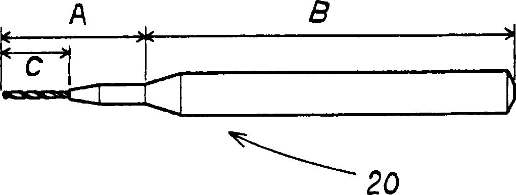
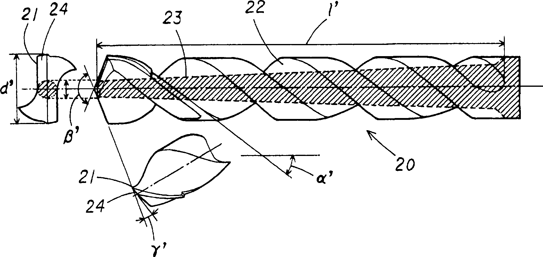
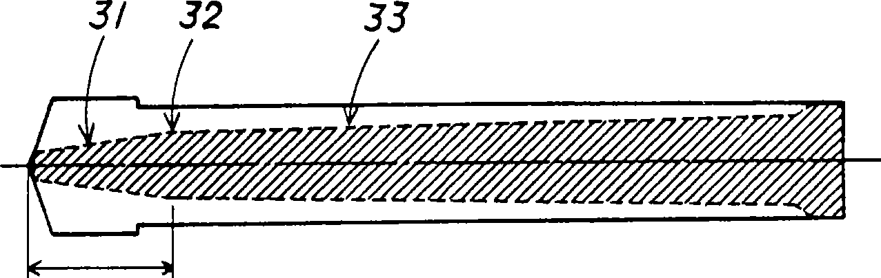
[0072] This embodiment is a drilling tool, the drilling tool is formed with one or more spiral chip removal grooves 2 from the front end of the tool toward the base end side on the outer periphery of the tool body 1, and the above chip removal grooves 2 include: first helix angle α 1 The first helical region 3; and the tool base end side of the first helical region 3 is continuously provided and has a ratio of the above-mentioned first helical angle α 1 Large second helix angle α 2 The second helical region 4 of the tool body 1 is configured such that the drill core thickness w gradually increases toward the base end side of the tool, and includes: a first tapered region 6 having a first drill core taper; The tool base end side of the region 6 is continuously provided and has a second tapered region 7 with a second core taper smaller than the first core taper, and ...


PUM

PropertyMeasurementUnit
Thicknessaaaaaaaaaa

Abstract

To provide a far more practical drilling tool that is capable of drilling holes having good hole position accuracy and hole wall roughness using a small-diameter drill of 0.4 mm or less. A drilling tool in which helical chip-evacuating flutes (2) are formed in the outer circumference of a tool main body (1), wherein the chip-evacuating flutes (2) have a first helical region (3) with a first helix angle +- 1 and a second helical region (4) with a second helix angle +- 2 greater than the first helix angle +- 1 , being provided on the tool base side of the first helical region (3); the tool main body 1 has a first taper region (6) with a first web taper and a second taper region (7) with a second web taper smaller than the first web taper, being provided on the tool base side of the first taper region (6); and a portion (8) where the first taper region (6) and the second taper region (7) are connected in a row is located more toward the tool base side than the portion (5) where the first helical region (3) and the second helical region (4) are connected in a row.

Description

technical field [0001] The invention relates to a drilling tool. Background technique [0002] For hole drilling of printed circuit boards (PCB), use figure 1 A drill consisting of a body portion A with a cutting edge C and a shank B is shown. Specifically, at blade C, such as figure 2 As shown, a helical chip flute 22 is formed on the outer periphery of the main body 20 from the front end of the drill to the base end side, and the rake surface of the chip flute 22 intersects with the first relief surface 24 provided at the front end. The wire portion is formed with a cutting edge 21 . In addition, reference numeral 23 is the drill core thickness formed by connecting the groove bottoms of chip flutes 22, d' is the drill diameter, is the flute length of the flute, α' is the helix angle, β' is the front angle, and γ' is the first clearance angle. [0003] In printed circuit boards, the required hole diameter is getting smaller year by year. In recent years, hole process...

Claims


Application Information

Patent Timeline
IPC IPC(8): B23B51/00
CPCB23B2251/404B23B2228/36B23B2251/046H05K3/0047B23B51/02B23B2251/426B23B51/011
Inventor 星幸义津坂英夫鸟越胜明
Owner UNION TOOL
Why Eureka
Try Eureka