Top roller carrying and loading arm

A technology of bearing parts and rollers, applied in the direction of textiles and papermaking, drafting equipment, spinning machines, etc., can solve the problems of high cost, achieve the effects of light weight, shock-absorbing operation, and simple production

Inactive Publication Date: 2009-05-13
SAURER COMPONENTS GMBH
View PDF1 Cites 6 Cited by
  • Summary
  • Abstract
  • Description
  • Claims
  • Application Information

AI Technical Summary

Problems solved by technology

This results in correspondingly hig

Method used


Image

  • Top roller carrying and loading arm
  • Top roller carrying and loading arm
  • Top roller carrying and loading arm

Examples


Embodiment Construction

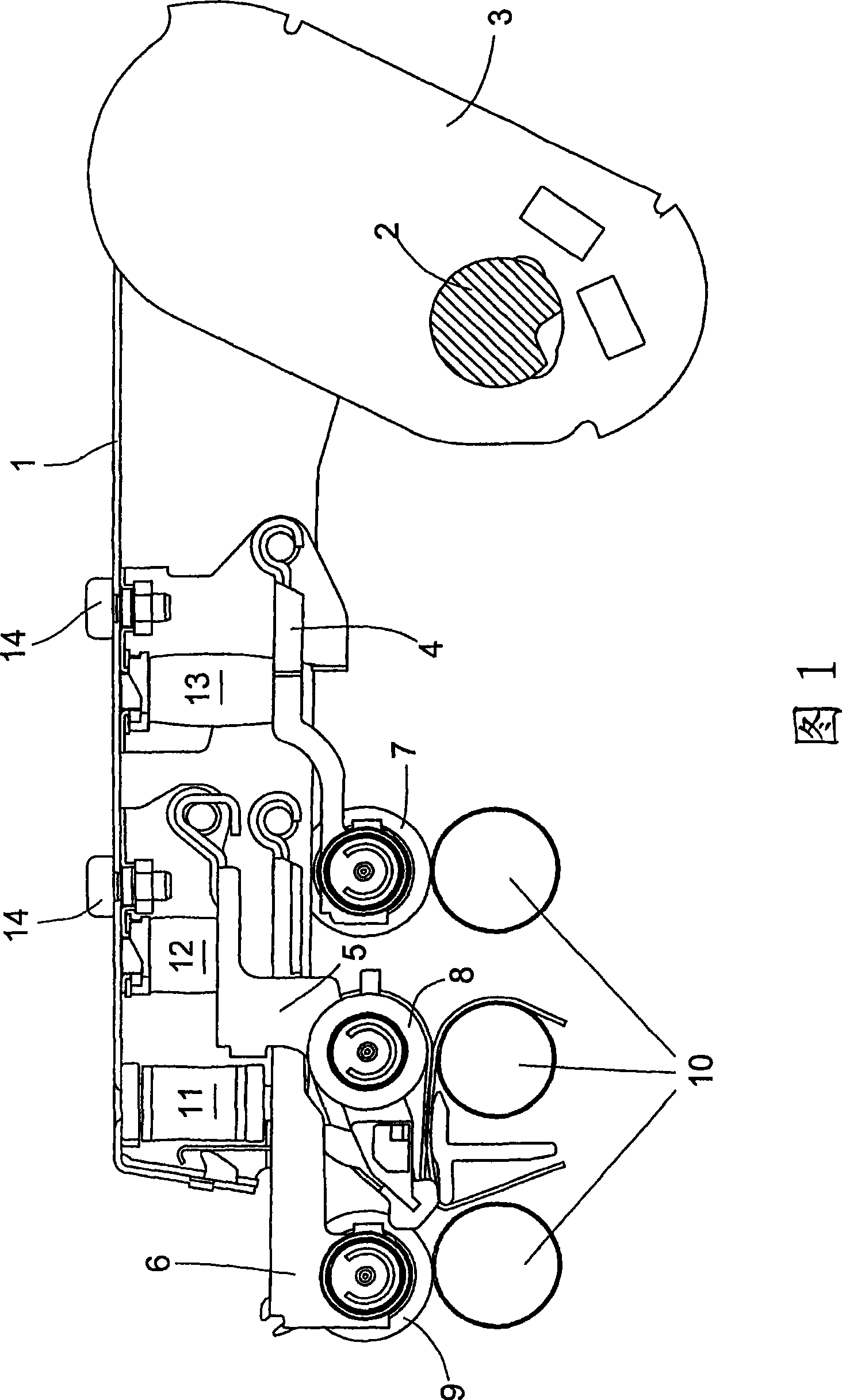
[0021] FIG. 1 shows a partial sectional view of a top roller carrier and a pressure arm 1 of a spinning machine drafting device with adjustable pressure elements for the top rollers 7 , 8 , 9 . The top roller carrier and the pressing arm 1 are pivotally mounted in a support 3 held on a fixed carrier bar 2 and can be actuated by a not shown operating lever. The pressing elements comprise guides 4, 5, 6 of top rollers arranged as a delivery roller 7, an intermediate roller 8 and a feed roller 9, respectively. The top rollers of the drafting device are designed as double rollers and are mounted with their shafts in the receptacles of the guides 4 , 5 , 6 . The guides 4 , 5 , 6 are pressed by resilient elastic compression springs 11 , 12 , 13 in the closed position of the top roller carrier and the pressing arm 1 .

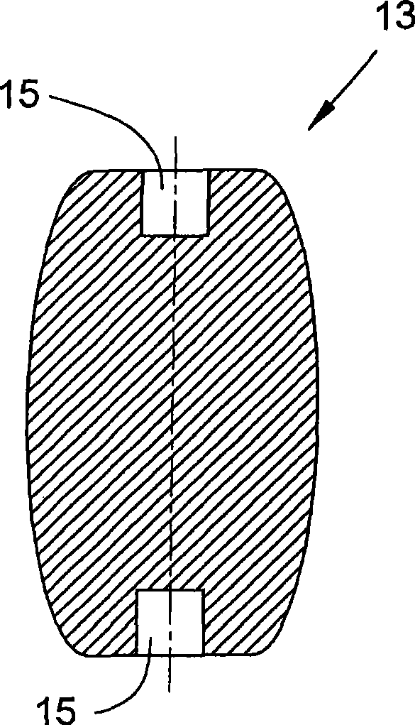
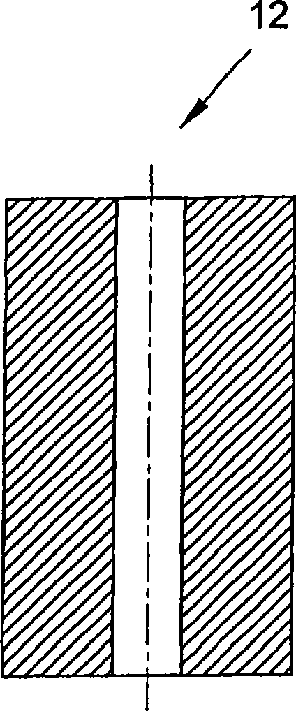
[0022] Compression springs 11, 12, 13 are made of plastic material and are substantially cylindrical. The compression springs 11 , 12 , 13 , which are formed as mol...


PUM


Abstract

The invention relates to a top roller carrying and loading arm (1) with guides (4, 5, 6) for receiving upper rollers (7, 8, 9) at a stretching unit. Fixture devices (4, 5, 6) are provided which are assigned with an elastic pressure springs (11, 12, 13) for loading the appropriate upper rollers, wherein the pressure springs (11, 12, 13) are constructed to plastic forming members.

Description

technical field [0001] The invention relates to a top roller carrier and a pressing arm according to the preamble of claim 1 . Background technique [0002] A drafting device of a spinning machine usually has a top roller carrier and a pressing arm, wherein the top roller can preferably be individually pressed by elastic elastic pressing elements. In order to obtain favorable operating conditions, the pressing pressure can be adjusted at the individual top rollers and adjusted to the respective spinning conditions. [0003] DE 42 432 92 Cl discloses such a top roller carrier and a pressing arm. The top roller carrier and the pressing arm have retaining devices for receiving the top rollers, wherein the spring force of the helical compression spring presses the respective retaining device so that the top roller is pressed against the corresponding bottom roller of the drafting device with a predeterminable force superior. The pressure adjustment for adapting to the differe...

Claims


Application Information

Patent Timeline
IPC IPC(8): D01H5/56
CPCD01H5/505D01H5/565
Inventor 阿尔佛雷德·尼德迈尔于尔根·施莱格尔
Owner SAURER COMPONENTS GMBH
Why Eureka
Try Eureka