Supercharge Your Innovation With Domain-Expert AI Agents!

Z-notch shape for a turbine blade

A technology of turbines and vanes, applied in the direction of supporting elements of blades, mechanical equipment, engine manufacturing, etc., which can solve problems such as maintenance and durability

Inactive Publication Date: 2009-05-13
GENERAL ELECTRIC CO
View PDF4 Cites 2 Cited by
  • Summary
  • Abstract
  • Description
  • Claims
  • Application Information

AI Technical Summary

Problems solved by technology

This is problematic from a maintenance and durability standpoint

Method used


Image

  • Z-notch shape for a turbine blade
  • Z-notch shape for a turbine blade
  • Z-notch shape for a turbine blade

Examples


Embodiment Construction

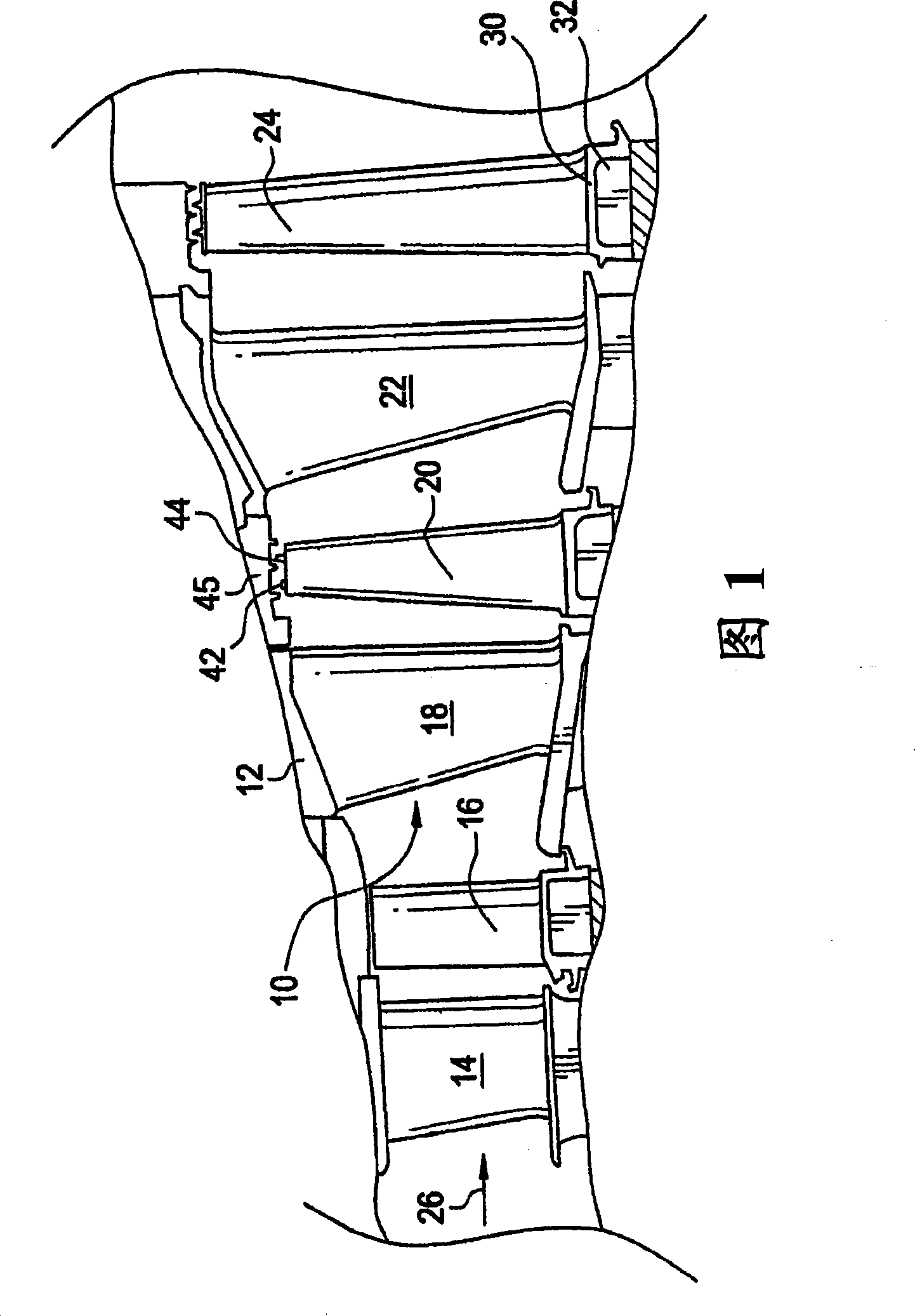
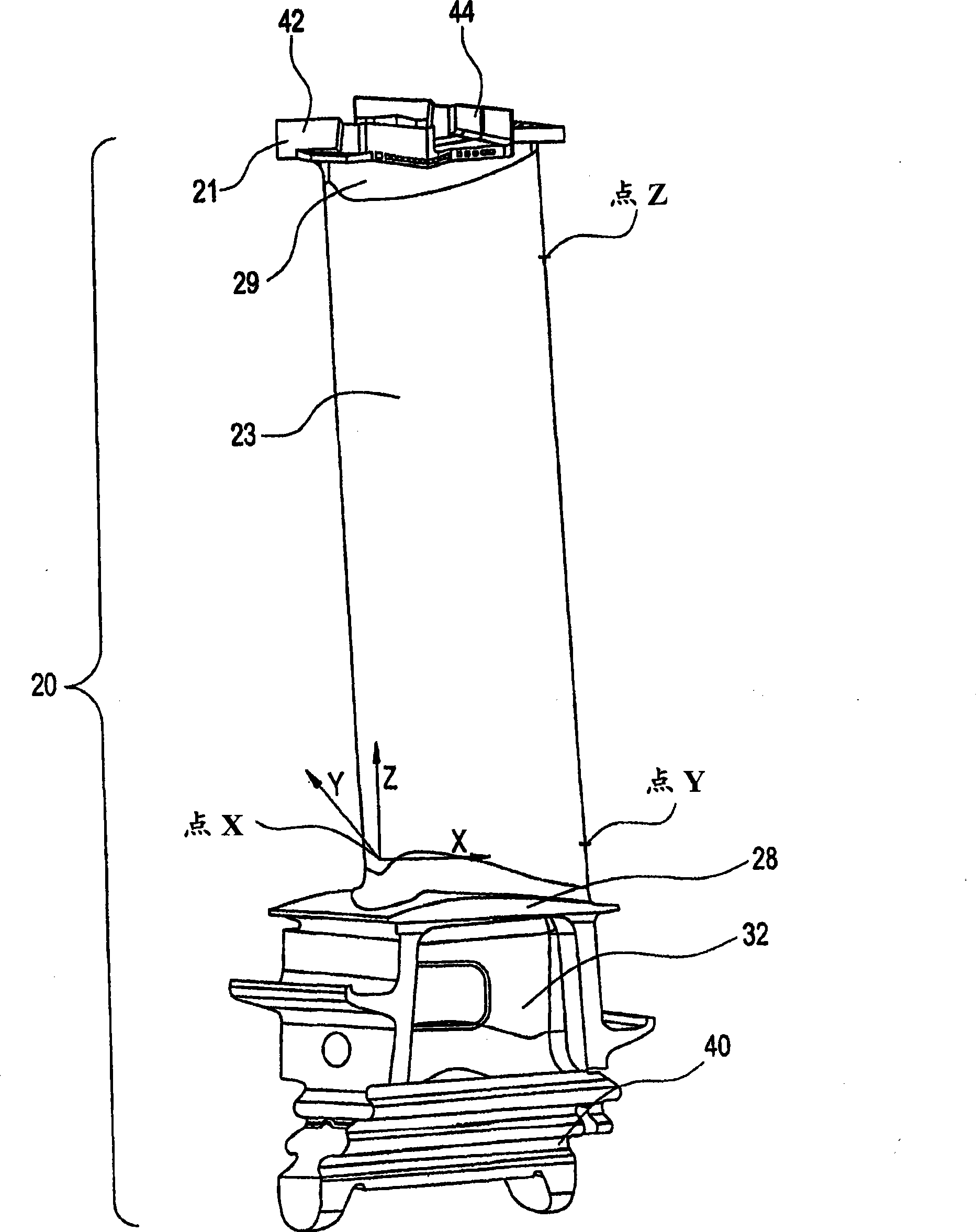
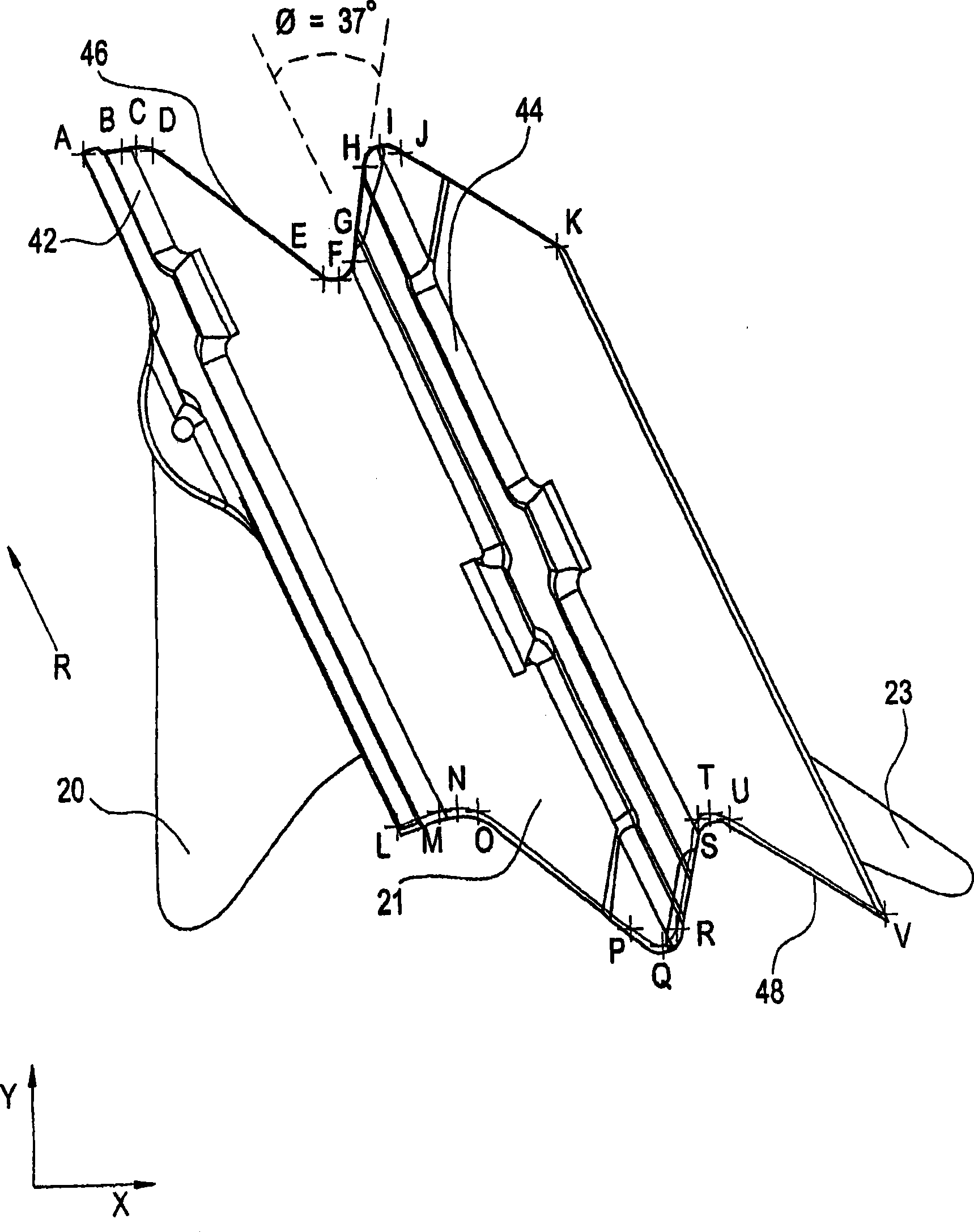
[0031] Disclosed is a design for a tip shroud for a turbine bucket. Known as the "Z-notch" design (or Z-notch profile), this design creates an interlocking condition between adjacent buckets during operation, providing engagement of adjacent buckets while reducing stress. The Z-notch design may be said to include a "Z-shaped profile". Among other things, the shaped profile of the Z-notch provides improved contact interaction between turbine blades in high-pressure turbines; improved mechanical blade loading under engine operating conditions; improved mass distribution in the tip shrouds, and Z-shape Improved control of any gaps between adjacent shrouds in the gap area. Some definitions are given before a detailed discussion of the embodiments.

[0032] The term "gas turbine" refers to a continuous combustion engine. In the exemplary embodiment, a gas turbine generally includes a compressor, a combustor (referred to as a "combustor"), and a turbine. During operation, the co...


PUM


Abstract

In one embodiment, buckets (16, 20, 24) of turbine (12) include: a tip shroud (21) with a front edge (46) and a following edge (48), the front edge (46) and the following edge (48) including a Z-Notch profile according to the Cartesian coordinate values of X, Y and Z set forth in Table I; wherein the coordinate values are dimensional values representing a distance from an origin of an internal coordinate system for the buckets (20); and wherein when the X and Y values are connected by smooth continuing arcs, the Z-Notch profile is defined. A turbine (12) is provided.

Description

technical field [0001] The present invention relates to gas turbine engines, and in particular to the design of shroud tips for turbine blades (ie, turbine buckets). Background technique [0002] Gas turbines include many moving parts, each of which may experience stress during operation. For example, a gas turbine includes a turbine for extracting energy from hot gases exhausted from a combustor. To extract this energy, multiple vanes are arranged in a series of stages. Each bucket includes multiple components. For example, each bucket typically includes an airfoil (as an energy-absorbing surface), a root (used to anchor the bucket to the shaft), and a shroud tip (to keep the blade centered during operation). [0003] The individual vanes are subjected to extremely high temperatures and mechanical stresses. These factors usually affect the entire blade. This is problematic from a maintenance and durability standpoint. For example, thermal expansion may induce a certai...

Claims


Application Information

Patent Timeline
Patent Type & Authority Applications(China)
IPC IPC(8): F01D5/14
CPCF01D5/22Y02T50/671F01D5/225F05D2250/74F01D5/141Y02T50/673Y02T50/60
Inventor R·A·布里廷厄姆A·I·安萨里
Owner GENERAL ELECTRIC CO
Features
  • R&D
  • Intellectual Property
  • Life Sciences
  • Materials
  • Tech Scout
  • Unparalleled Data Quality
  • Higher Quality Content
  • 60% Fewer Hallucinations
Learn More