Inverse defrosting method for air supply heat pump

A reverse defrosting and heat pump technology, applied in heat pumps, lighting and heating equipment, compressors with reversible cycles, etc., can solve problems affecting performance, wasting energy, affecting heat transfer of evaporators, etc., to achieve energy efficiency ratio optimization and saving energy effect

Active Publication Date: 2010-06-09
SHENZHEN POWER WORLD NEW ENERGY TECH
View PDF4 Cites 2 Cited by
  • Summary
  • Abstract
  • Description
  • Claims
  • Application Information

AI Technical Summary

Problems solved by technology

[0004] However, since the degree of frosting of the heat pump is affected by factors such as ambient temperature and ambient humidity, and if the energy efficiency ratio of defrosting is considered, the following problems may occur in the timing and time-consuming selection of defrosting: 1. Too frequent defrosting, although it can ensure that the heat pump unit will not be unable to heat due to thickening of frost, but it will consume too much energy in the defrosting action, wasting energy; if the heating time is too long and delayed If defrosting is not performed, the low pressure protection may trip due to too thick frost, or the thick frost layer will affect the heat transfer of the evaporator, thereby affecting the performance
Obviously, the fixed heating operation cycle of the traditional method cannot accurately reflect the frosting situation of the evaporator. For example, when the ambient temperature is low and the humidity is high, the frosting situation of the evaporator after one operation cycle has seriously exceeded expectations. If the heating performance is compromised, it will cause unnecessary energy consumption; another example is that the humidity of the environment is low, and the evaporator has little frost after one operation cycle. At this time, it is not necessary to enter the defrosting, which will also cause energy waste.

Method used


Image

  • Inverse defrosting method for air supply heat pump
  • Inverse defrosting method for air supply heat pump
  • Inverse defrosting method for air supply heat pump

Examples


Embodiment Construction

[0024] Example of reverse defrosting device:

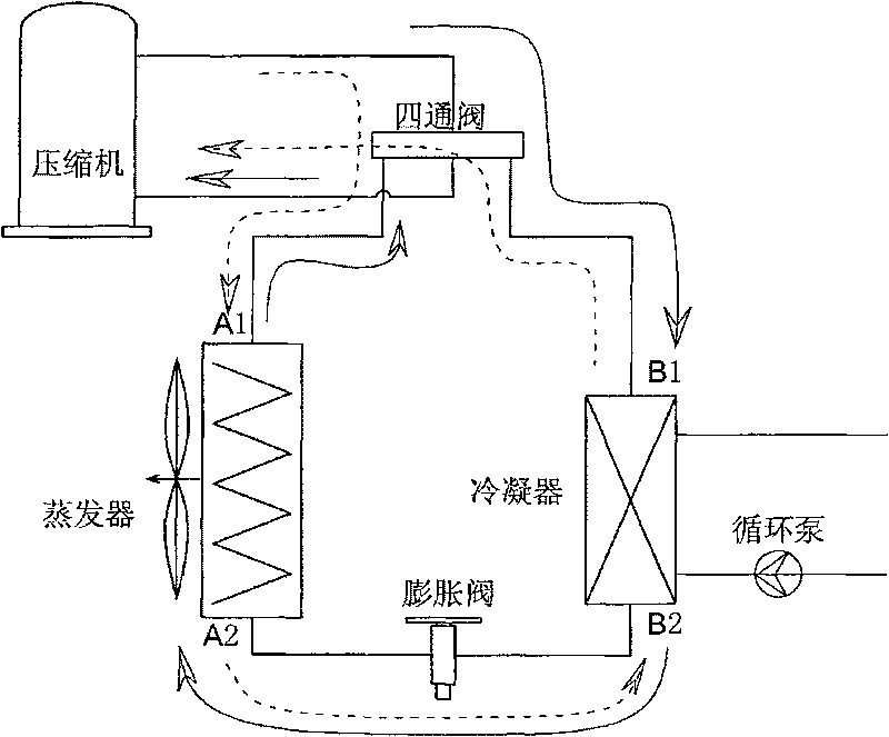
[0025] Such as figure 1 , which is a schematic structural diagram of an embodiment of the reverse defrosting device of the present invention. The air source heat pump includes a controller, a compressor, an evaporator, an expansion valve, a condenser and a circulating pump, and an electric-controlled four-way valve is connected in series between the outlet and the inlet of the compressor, and the electric-controlled four-way valve The other two interfaces of the condenser are respectively connected to the refrigerant ports A1 and B1 of the condenser and the evaporator, and the other refrigerant ports A2 and B2 of the condenser and the evaporator are connected to each other through the expansion valve, and the controller is respectively connected to The switching circuit of the electronically controlled four-way valve, compressor, evaporator, and circulating pump is characterized in that: the reverse defrosting method includes: th...


PUM


Abstract

The invention relates to a reverse defrosting method of an air source heat pump. The air source heat pump comprises a controller, a compressor, an evaporator, an expansion valve, a condenser and a circulating pump thereof, and an electric control four-way valve is serially connected between an outlet and an inlet of the compressor. The defrosting method comprises the following steps: the controller controls the electric control four-way valve, the compressor, the evaporator and the circulating pump to act sequentially and perform the following sequential steps repeatedly and alternately: heating, stopping to switch the valves, defrosting, and stopping to switch the valves again; and the reverse defrosting method further comprises the following steps: A) the controller records the time T1 of the heating step in the previous circle and the time t consumed in the subsequent defrosting step; and B) the time T2 of the heating step in the next circle is set after computation according to theoptimum defrosting time b which is obtained by experiments. The air source heat pump can automatically adjust heating operation period, defrosting start time and defrosting time according to the ambient conditions by the reverse defrosting method so as to obtain the optimum energy efficiency ratio.

Description

technical field [0001] The invention relates to a heat pump device, more specifically, the invention relates to a reverse defrosting device of an air source heat pump and a control method thereof. Background technique [0002] When the air source heat pump operates in a low-temperature climate, when the temperature and humidity reach certain conditions, frost will form on the surface of the evaporator. As time goes by, if the frost layer is not removed, the frost will become thicker and thicker, so that it will gradually affect the surface of the evaporator. The heating performance of the heat pump, until it can no longer perform heating work. [0003] Frosting will reduce the heat transfer performance of the evaporator and increase the energy consumption of heating. Therefore, when the frost is formed to a certain extent, it needs to consume extra energy to remove the frost layer of the evaporator, and then resume heating. At present, the common method of traditional rever...

Claims


Application Information

Patent Timeline
Patent Type & Authority Patents(China)
IPC IPC(8): F25B47/02F25B49/02F25B13/00F25B30/06
Inventor 粱守棋
Owner SHENZHEN POWER WORLD NEW ENERGY TECH
Why Eureka
Try Eureka