Device and method for generating directional sound

A technology for generating devices and directional sound, which is applied in the field of directional sound, can solve problems such as high cost and complicated directional sound technology, and achieve the effects of simple structure, good integration, energy efficiency ratio, and low distortion

Active Publication Date: 2019-06-18
SOUNDAI TECH CO LTD
View PDF6 Cites 0 Cited by
  • Summary
  • Abstract
  • Description
  • Claims
  • Application Information

AI Technical Summary

Problems solved by technology

[0004] At present, the technologies for generating directional sound are relatively complicated and costly. They are generally used in the military field, and almost no one is used in civilian applications.

Method used


Image

  • Device and method for generating directional sound
  • Device and method for generating directional sound
  • Device and method for generating directional sound

Examples


Embodiment 1

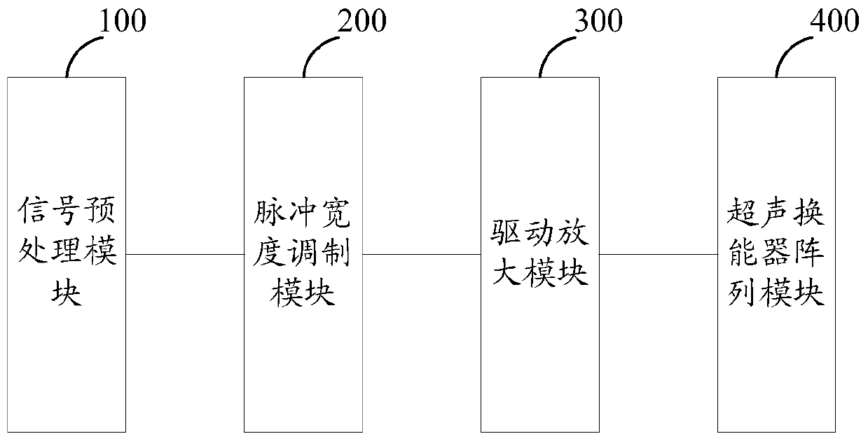
[0049] see figure 1 , which is a schematic diagram of Embodiment 1 of the directional sound generating device provided by the present invention.

[0050] The directional sound generating device provided in this embodiment includes: a signal preprocessing module 100, a pulse width modulation module 200, a drive amplification module 300 and an ultrasonic transducer array module 400;

[0051] The signal preprocessing module 100 is used to sequentially perform bandpass filtering, gain amplification, low frequency compensation, and compression and limiting processing on the input digital audio signal, and send the processed signal to the pulse width modulation module;

[0052] It should be noted that the signal preprocessing module 100 receives a digital audio signal. If the directional sound generating device receives an analog audio signal, it needs to go through an AD converter to convert the analog audio signal into a digital audio signal, and then send it to the signal Preproce...

Embodiment 2

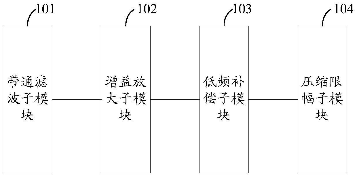
[0063] see figure 2 , which is a schematic diagram of the internal structure of the signal preprocessing module provided by the present invention.

[0064] The signal preprocessing module provided in this embodiment includes: a bandpass filtering submodule 101, a gain amplification submodule 102, a low frequency compensation submodule 103, and a compression and limiting submodule 104;

[0065] The band-pass filtering sub-module 101 is used to band-pass filter the input digital audio signal, and filter out signals other than the cut-off frequency;

[0066] Gain amplification sub-module 102, used to amplify the signal output by the band-pass filter sub-module;

[0067] The low-frequency compensation sub-module 103 is configured to perform low-frequency compensation on the signal output by the gain amplification sub-module;

[0068] The compression and limiting sub-module 104 is configured to perform compression and limiting on the signal after gain amplification.

[0069] It...


PUM


Abstract

The invention provides a directional sound generating apparatus and method. The apparatus comprises: a signal preprocessing module for successively performing bandpass filtering, gain amplifying, low-frequency compensating and compression amplitude limiting processing on input digital audio signals and sending the processed signals to a pulse-width modulation module; the pulse-width modulation module for obtaining modulated ultrasonic carrier wave signals from the processed signals by use of pulse-width modulation; a driving amplification module for performing driving amplification on the modulated ultrasonic carrier wave signals; an ultrasonic transducer array module for matching the amplified modulated ultrasonic carrier wave signals with an ultrasonic sensor array through an LC low-pass filtering circuit to emit ultrasonic signals and generating directional sound by use of nonlinear propagation of the ultrasonic signals in air, wherein the ultrasonic sensor array in an ultrasonic energy transducer comprises multiple array elements, and the carrier wave frequency of the ultrasonic carrier wave signals are arranged according to the work frequency of each array element. The pulse-width modulation structure is quite simple, the distortion is quite small, and the integration and the energy efficiency ratio are good.

Description

technical field [0001] The invention relates to the technical field of directional sound, in particular to a device and method for generating directional sound. Background technique [0002] Directional sound technology is a technology that controls the directional transmission of sound waves in a certain area of ​​space. Unlike the sound waves emitted by traditional speakers that propagate in all directions, directional sound technology can only transmit sound in a specific area, but outside the specific area. Then the attenuation is very fast, and the sound can hardly be heard, so it has better privacy and reduces the generation of noise, and has wide application prospects in military and civilian fields. [0003] Some studies on directional sound technology have been carried out at home and abroad, mainly based on two parametric acoustic array theories of Westervelt equation and Berktay far-field solution, using the nonlinear effect of ultrasonic propagation in the air to...

Claims


Application Information

Patent Timeline
Patent Type & Authority Patents(China)
IPC IPC(8): H04R1/32H04R3/00
Inventor 常乐常鑫陈宏
Owner SOUNDAI TECH CO LTD
Why Eureka
Try Eureka