Unlock instant, AI-driven research and patent intelligence for your innovation.

Connection terminal structure

A terminal and terminal technology, which is applied in the field of electricity, can solve the problems of too many exposed wires, no identification of incoming and outgoing wires on the terminal, and weak connection, etc., and achieve the effect of convenient use, simple structure and accurate positioning

Active Publication Date: 2011-09-14
SHANGHAI UPUN ELECTRIC GRP
View PDF0 Cites 0 Cited by
  • Summary
  • Abstract
  • Description
  • Claims
  • Application Information

AI Technical Summary

Problems solved by technology

[0003] The purpose of the present invention is to provide a structure of a connection terminal, which solves the technical problems in the prior art that the connection terminal has no mark of incoming and outgoing wires, too many wires are exposed, and the connection is not firm.

Method used


Image

  • Connection terminal structure
  • Connection terminal structure
  • Connection terminal structure

Examples


Embodiment Construction

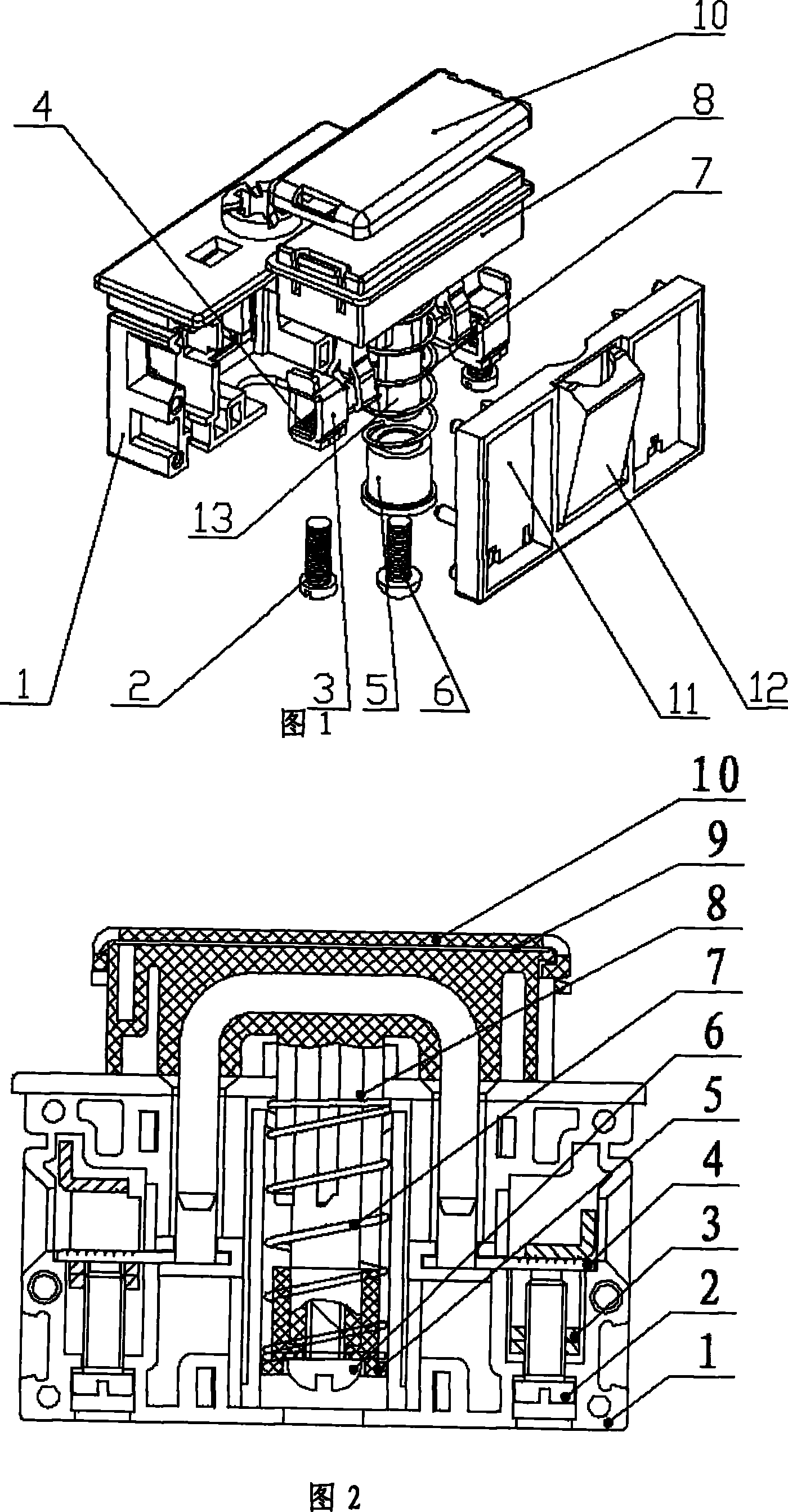
[0017] Such as figure 1 , figure 2 , image 3 , Figure 4 with Figure 5 As shown, the structure of a terminal of the present invention is composed of an insulating housing, a protective cover 10 and a terminal. The insulating member is composed of a perforated insulating member 1 and a pillared insulating member 11. The component 11 is matched with the perforated insulating component 1, the protective cover 10 is arranged on the upper part of the insulating housing, and the terminal is arranged inside the insulating housing, wherein the A connecting handle 8 is arranged between the perforated insulating member 1 and the columned insulating member 11. The protective cover 10 is arranged on the upper part of the connecting handle 8, and at the lower part of the connecting handle 8, located in the A spring column 13 is provided inside the insulator, a seat 5 is sleeved on the lower part of the spring column 13, a spring 7 is sleeved on the outer periphery of the seat 5, and a sc...


PUM


Abstract

A structure of a wire connecting terminal comprises an insulating casing and two binding posts. A connection handle is arranged in the insulating casing; a strut is connected on the lower side of the connection handle; a screw is arranged at the lower end of the strut; a strut base is sheathed at the lower part of the strut; the strut base is fixedly connected with an insulating piece with a holeand an insulating piece with a post; the peripheries of the strut base and the strut are respectively sheathed with a spring; the two binding posts are respectively formed by line pressing frames; the line pressing frames are respectively arranged at two sides of the strut, and respectively connected with the insulating casing; conducting strips are arranged in the line pressing frames; and compression screws are arranged on the line pressing frames. The line pressing frames are arranged in the insulating casing, so that the structure of the invention can be conveniently and firmly connected conductive wires; and a marking paster is arranged on the connection handle or a protecting cover, so that leading-in and leading-out directions can be accurately displayed. Furthermore, the inventionhas the advantages of simple structure, accurate positioning, convenient use, safety and reliability.

Description

Technical field: [0001] The present invention relates to the field of electricity, in particular to an electrical connection piece, in particular to the structure of a connection terminal. Background technique: [0002] In electrical equipment, the switching of the loop on or off needs to be realized by the terminal block. In the prior art, the incoming terminal and the outgoing terminal of the electrical connection have no obvious identification, which causes inconvenience when used at the construction site; at the same time, the wiring terminal adopts the plugging method to connect the wires, which is not strong enough, and the wiring terminal cannot protect the connected wires , The wires have more exposed parts, which poses safety risks. Summary of the invention: [0003] The purpose of the present invention is to provide a structure of a connecting terminal, which is to solve the technical problems in the prior art that the connecting terminal has no identification of incomi...

Claims


Application Information

Patent Timeline
Patent Type & Authority Patents(China)
IPC IPC(8): H01R13/04H01R4/38H01R13/629
Inventor 王国良赵建余
Owner SHANGHAI UPUN ELECTRIC GRP
Features
  • R&D
  • Intellectual Property
  • Life Sciences
  • Materials
  • Tech Scout
  • Unparalleled Data Quality
  • Higher Quality Content
  • 60% Fewer Hallucinations
Learn More