Cable clamper

A technology of cable clamps and splints, which is applied in the field of power circuits, can solve the problems of small cable contact area, cable mechanical damage, and high cable pressure, and achieve the effects of reducing cable damage, ensuring cable protection, and increasing the clamping area

Inactive Publication Date: 2009-05-13
JIANGSU ELECTRIC POWER CO
View PDF0 Cites 2 Cited by
  • Summary
  • Abstract
  • Description
  • Claims
  • Application Information

AI Technical Summary

Problems solved by technology

However, some problems in actual use should also be considered: whether the gripping force can satisfy the cable to slide freely when encountering thermal expansion and contraction; Situation etc.
The cables are often laid with different arcs of different sections. Therefore, when the original clamp is used to clamp a large-section cable, the clamping force on the cable at both ends of the clamp is much greater than that of the cable in the middle of the clamp. The compression force of the cable is concentrated at both ends of the fixing fixture. The contact area of ​​the cables at both ends of the existing fixing fixture is very small. Under a certain force, due to the small contact area, the pressure on the cable is very large, which is easy to cause mechanical damage to the cable.

Method used


Image

  • Cable clamper
  • Cable clamper
  • Cable clamper

Examples


Embodiment Construction

[0020] The present invention will be further described below in conjunction with the accompanying drawings and specific embodiments.

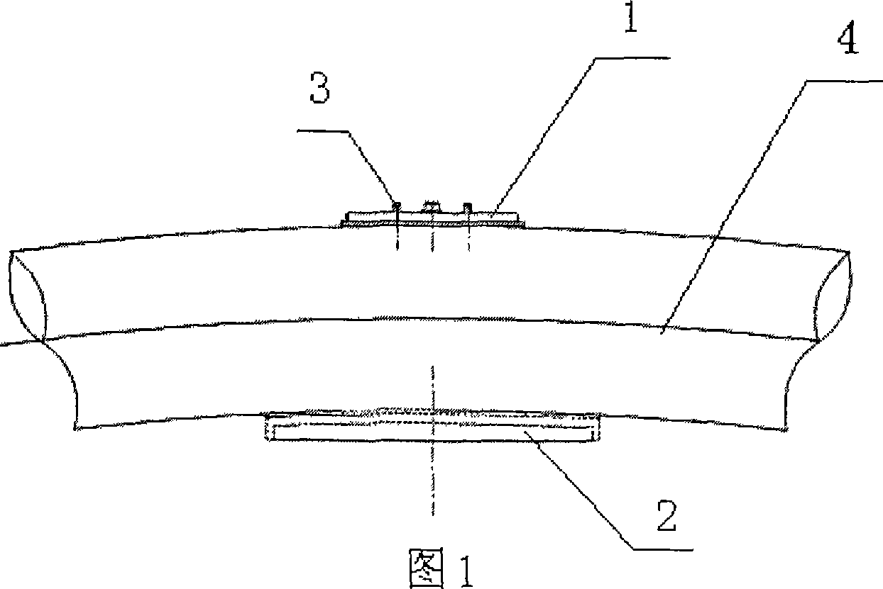
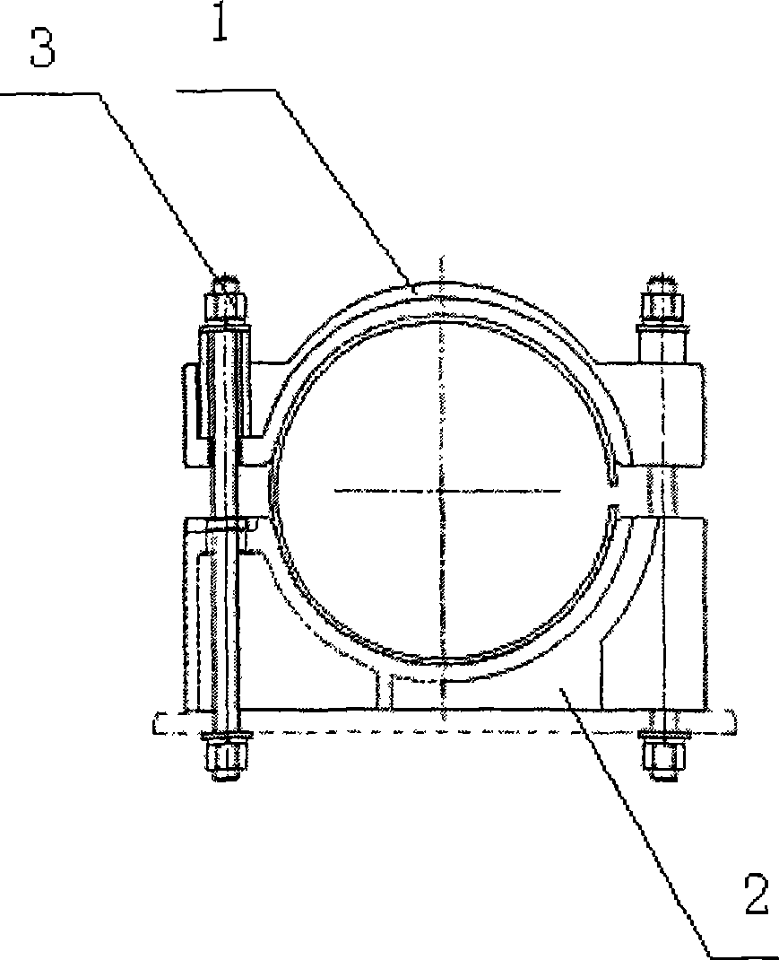
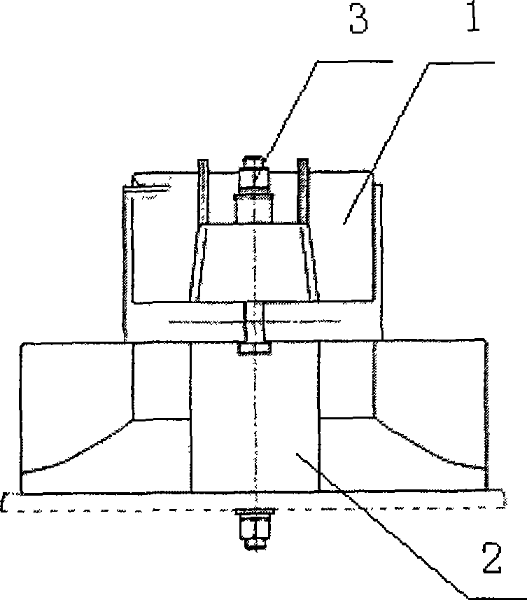
[0021] A cable clamp includes two semicircular splints (ie, the upper splint and the lower splint in the figure). The cross-sectional shape of the splints is part of the same ring, and they are connected to each other to form a hollow where cables can be placed. One of the two splints is longer than the other. The axial section of the longer splint (lower splint) is arc-shaped. The position of the shorter splint (upper splint) corresponds to the vault position of the longer curved splint (lower splint). The back of the curved splint is opposite to the shorter splint. The inner surface of the splint is provided with a protective pad. The two splints are connected by bolts.

[0022] In this example, the clamp material is preferably aluminum alloy. Liners or protective pads can be rubber, plastic, lead plates and wooden washers, and plastic s...


PUM


Abstract

A cable clamp includes two semicircular clamping plates, wherein, the section shape of the clamping plates is one part of the same circle and the clamping plates are connected mutually to form a hollow for accommodating cables. One clamping plate is longer than the other clamping plate. The invention can efficiently ensure cable fixation and cable protection.

Description

technical field [0001] The invention belongs to the technical field of power circuits, in particular to a cable clamp suitable for vertical wave laying of 220KV large-section power cables. Background technique [0002] In the existing technology, the use of urban cable tunnels is increasing day by day. According to the relevant experience at home and abroad and the principle of saving space, most cables are laid in vertical waves, and the fixing of cables and cable supports is very important. During the fixing process, the key lies in the selection and installation requirements of the hoop. In the past, hoops were generally made of wood or plastic structures, and their light weight and easy installation became the reason for long-term use. In recent years, the application of aluminum alloy hoops is gradually developing and growing. Its advantage is that it is light, non-perishable and has a certain mechanical strength, and it has a moderate grip on the cable. Taking advan...

Claims


Application Information

Patent Timeline
Patent Type & Authority Applications(China)
IPC IPC(8): H02G9/08
Inventor 王光明陈德风孙维路黄淑铭张行
Owner JIANGSU ELECTRIC POWER CO
Why Eureka
Try Eureka