
Optical signal equalizer with adjustable linear filter

A filter and signal conditioner technology, applied in the field of signal transmission, can solve the problem of unreadable electronic signals

Inactive Publication Date: 2009-05-13
FINISAR
View PDF0 Cites 5 Cited by
  • Summary
  • Abstract
  • Description
  • Claims
  • Application Information

AI Technical Summary

Problems solved by technology

For example, a small 7-10 inch transmission line formed on a printed circuit board may cause enough dispersion in an electronic signal traveling at 10 gigabits per second to effectively render the electronic signal unreadable

Method used


Image

  • Optical signal equalizer with adjustable linear filter
  • Optical signal equalizer with adjustable linear filter
  • Optical signal equalizer with adjustable linear filter

Examples


Embodiment Construction

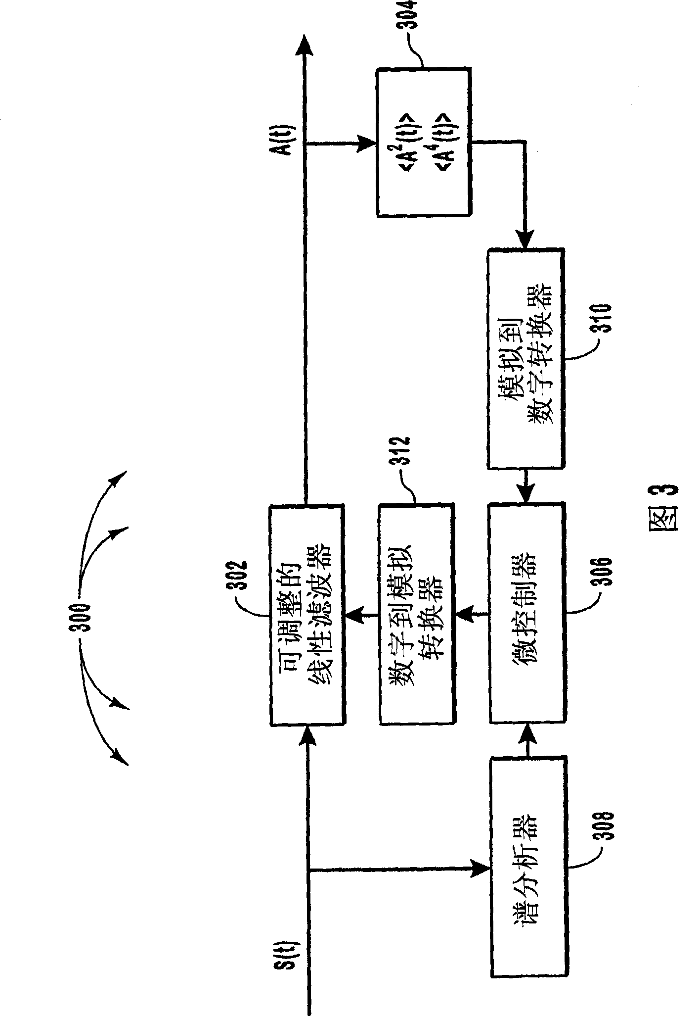
[0018] Embodiments of the present invention compensate for dispersion-related effects caused by communication channels. Embodiments pass the signal traveling on the channel through a linear filter. Linear filters are designed to counteract dispersion-related effects. These embodiments calculate a figure of merit for the signal output from the linear filter. The figure of merit may be a function of the second and fourth moments of the output. Based on the value of the figure of merit, the coefficients of the linear filter can be adjusted in order to improve the performance of the linear filter.

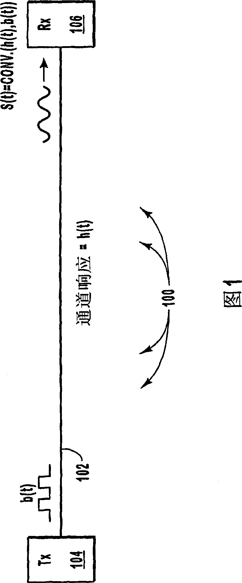
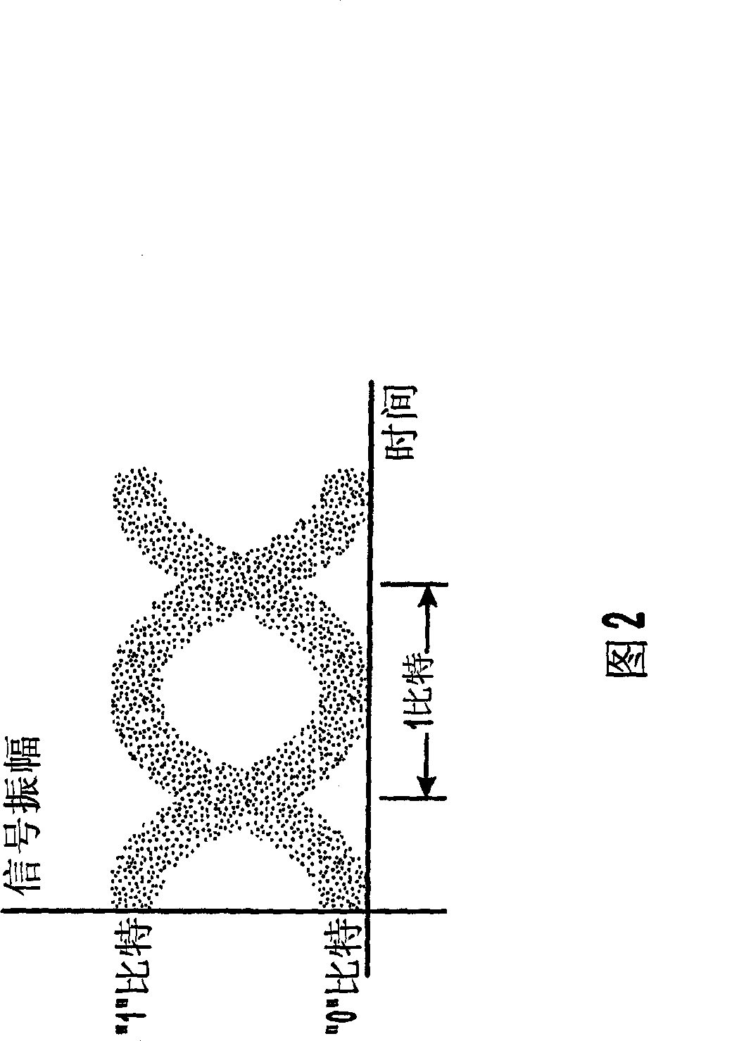
[0019] An example of optical signal dispersion is shown in FIG. 1 , which schematically illustrates a fiber optic communication path 100 . The data signal b(t) propagates through the transmitter 104 onto the fiber optic cable 102 . As the data signal b(t) propagates onto the fiber optic cable 102, the transition between high and low logic bits is steep. As the data signal b(t) tra...


PUM


Abstract

Mitigating errors caused by the dispersion of optical or electrical signals. Errors caused by dispersion in high frequency system are mitigated by passing a received signal through an adjustable linear filter that counteracts a channel response of a channel on which the received signal has traveled to produce an electrical signal. The adjustable linear filter has a number of coefficients. A figure of merit is calculated for the electrical signal, where the figure of merit includes the second and fourth moments of the electrical signal. The coefficients of the linear filter are adjusted based on the value of the figure of merit so as to minimize the figure of merit.

Description

technical field [0001] The present invention relates generally to signal transmission in communication systems. More specifically, the present invention relates to systems and methods for mitigating dispersion effects in high frequency communication systems. Background technique [0002] In the field of data transmission, one method of efficiently transferring data is through the use of optical fibers. Digital data travels through fiber optic cables using light emitting diodes or lasers. In order to send data over a fiber optic cable, the data is typically converted from electronic data generated by a computer to optical data that can be propagated over the fiber optic cable. This conversion is usually performed using lasers or light emitting diodes. A logic "1" is represented when light is generated (or at "high power"). No light (or light at "low power") represents a logic "0". Thus, an optical signal with sharp rising and falling transitions representing logic "1" an...

Claims


Application Information

Patent Timeline
Patent Type & Authority Applications(China)
IPC IPC(8): H04B1/10G02BH04B10/18H04B10/2581
CPCH04B10/2581H04B10/25133
Inventor 托马斯·莱诺斯基
Owner FINISAR
Learn More