Bulk acoustic wave mediated multiferroic antennas

a multi-ferroic, acoustic wave technology, applied in the direction of antennas, antenna couplings, electrical devices, etc., can solve the problems of difficult matching of antennas, poor radiation of antennas, and elevated radiation q factor

Active Publication Date: 2018-04-26
RGT UNIV OF CALIFORNIA
View PDF5 Cites 20 Cited by
  • Summary
  • Abstract
  • Description
  • Claims
  • Application Information

AI Technical Summary

Benefits of technology

[0013]In this disclosure, BAW resonance modes are formed vertically across the layers and they are called as the “thickness modes”. Analyses of this technique shows that, the radiation quality factor of these BAW mediated antennas can be significantly lowered with high permeability and a high magnetic to mechanical coupling figure of merit in the magnetostrictive material, which thus allows creation of low-profile antennas with high radiation efficiency.

Problems solved by technology

These antennas, however, radiate poorly when placed at a short distance above a conducting plane.
The platform effect is also described by the excessive storage of reactive energy between the radiating element and the platform, which elevates the radiation Q factor and makes the antenna difficult to match.
However, these proposed techniques fail to overcome issues with antenna radiation efficiency in close proximity to a conducting plane.

Method used


Image

  • Bulk acoustic wave mediated multiferroic antennas
  • Bulk acoustic wave mediated multiferroic antennas
  • Bulk acoustic wave mediated multiferroic antennas

Examples


Embodiment Construction

[0022]1. Introduction.

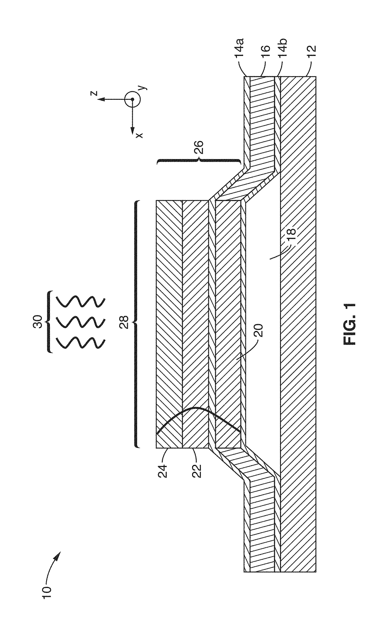
[0023]FIG. 1 illustrates an example embodiment 10 of BAW based multiferroic radiating elements, comprising a sandwich 26 of three layers of materials disposed in close proximity over a substrate (base) 12 material. Of these three layers, bottom layer 20 is a piezoelectric material, the middle layer is a magnetostrictive material 22, and an optional top layer 24 provides an acoustic buffer layer (or inertial buffer layer), such as comprising a material having a similar acoustic property to that of the piezoelectric material layer. The acoustic properties of this third layer are sufficiently similar to allow sufficient acoustic excitation and resonance so that this third layer acts as a counter mass during resonance.

[0024]It should be appreciated that this embodiment uses two layers of material up to a multiplicity of layers, interleaving piezoelectric materials of the same or different types with magnetostrictive materials of the same or different types. The mat...


PUM


Abstract

An antenna apparatus utilizing bulk acoustic wave (BAW) resonances to transfer dynamic strain across multiple layers, which include piezoelectric layers coupled to magnetostrictive material layers. In at least one embodiment, a piezoelectric layer is coupled to a magnetostrictive layer to which another layer having similar acoustic properties as the piezoelectric layer is coupled as an inertial buffer. These multiple layers comprise a strain media to provide a vertical multiferroic coupling which couples electric field, magnetic field, and mechanical fields. Electrodes are coupled to excite one of the piezoelectric layers for injecting acoustic waves into the structure from which electromagnetic radiation is generated out of the plane.

Description

CROSS-REFERENCE TO RELATED APPLICATIONS[0001]This application claims priority to, and the benefit of, U.S. provisional patent application serial number 62 / 172,304 filed on Jun. 8, 2015, incorporated herein by reference in its entirety.STATEMENT REGARDING FEDERALLY SPONSORED RESEARCH OR DEVELOPMENT[0002]This invention was made with Government support under 1160504, awarded by the National Science Foundation. The Government has certain rights in the invention.INCORPORATION-BY-REFERENCE OF COMPUTER PROGRAM APPENDIX[0003]Not ApplicableNOTICE OF MATERIAL SUBJECT TO COPYRIGHT PROTECTION[0004]A portion of the material in this patent document is subject to copyright protection under the copyright laws of the United States and of other countries. The owner of the copyright rights has no objection to the facsimile reproduction by anyone of the patent document or the patent disclosure, as it appears in the United States Patent and Trademark Office publicly available file or records, but otherw...

Claims


Application Information

Patent Timeline
Patent Type & Authority Applications(United States)
IPC IPC(8): H01Q7/06H03H9/17H03H9/22
CPCH01Q7/06H03H9/173H03H9/22H01Q3/44H01Q1/52H01Q7/00
Inventor WANG, YUANXUN ETHANCARMAN, GREGORY P.CANDLER, ROBERT NORRISKELLER, SCOTT
Owner RGT UNIV OF CALIFORNIA
Why Eureka
Try Eureka