[0004]It is a general object of the present invention to provide an RFID transponder which is capable of transmitting and receiving data efficiently during both uplink and downlink
data transmission.
[0006]Further, the RFID transponder can be adapted to have a high quality factor also during a charging phase, when the RFID transponder is charged by an electromagnetic wave received through the antenna. A high quality factor allows the RFID transponder to be charged more efficiently and over larger distances than a low quality factor. Therefore, the RFID transponder according to an aspect of the present invention is preferably adapted to be switched into a high quality factor mode during the charging phase. This implies, however, that for passive transponders, which are supplied exclusively by electromagnetic
waves, the quality factor is to be set to a high value during initialization.
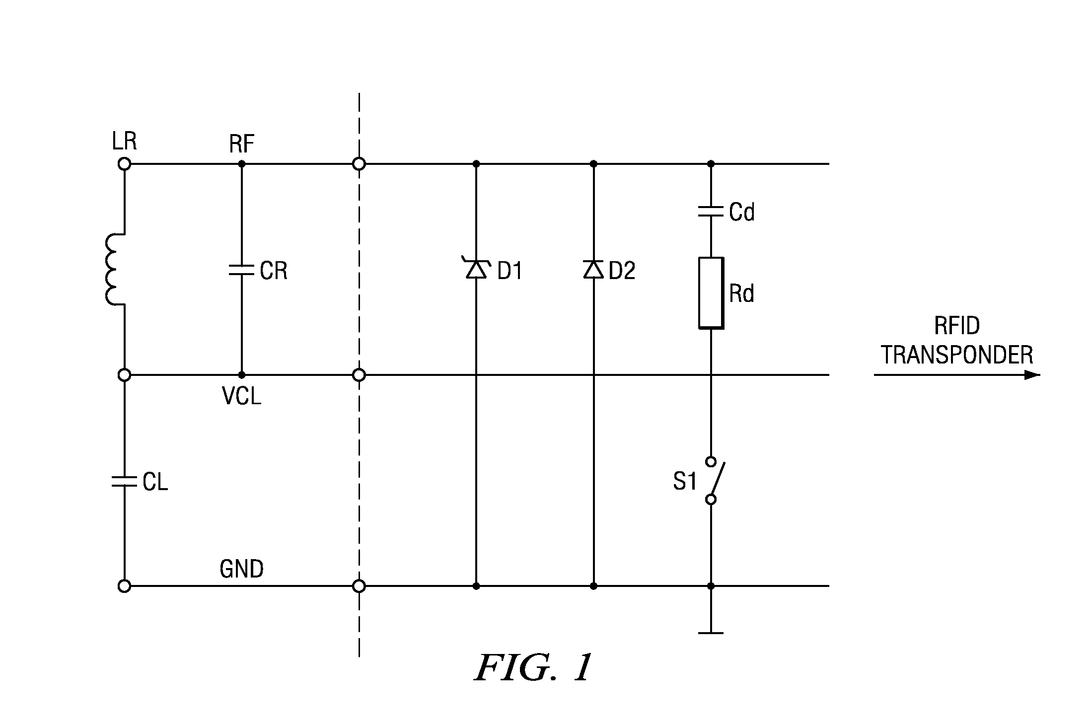
[0007]In order to switch the quality factor of the resonant circuit between a high quality factor and a low quality factor, according to an aspect of the invention, a series of a damping capacitor and a damping
resistor can be switched in parallel to the resonant circuit. Therefore, a switch can be coupled in series to the damping capacitor and the damping
resistor, in order to selectively switch the series of damping capacitor and damping resistor on and off, i.e. in parallel configuration to the resonant circuit for damping. Actually, the serial combination of damping resistor and capacitor can be connected to the resonant circuit (i.e. to a node at which the capacitor and the
inductor are connected) and to ground via a switch in order to reduce the quality factor. A series of a damping capacitor and a damping resistor is more
power efficient than a sole damping resistor. If the series of damping capacitor and damping resistor is coupled to the resonant circuit, the resonant circuit has a low quality factor. Without having the series of damping capacitor and damping resistor coupled to the resonant circuit and to ground, the resonant circuit has a high quality factor.
[0010]Also, a start-stop stage may be provided in the RFID transponder, which is adapted to start an oscillation
maintenance stage to maintain the resonant circuit oscillation when the quality factor is high and when the end of burst stage has detected the absence of a burst of a received RF
signal (i.e. during OFF periods but in high Q mode). Furthermore, during uplink data transmission the start-stop stage starts the oscillation
maintenance stage. Generally, the oscillation
maintenance stage can use the resonant circuit as an oscillator during OFF periods and provides a respective internal excitation of the resonant circuit. This maintained oscillation of the resonant circuit can then be used as a basis for a reference
clock, while the external RF
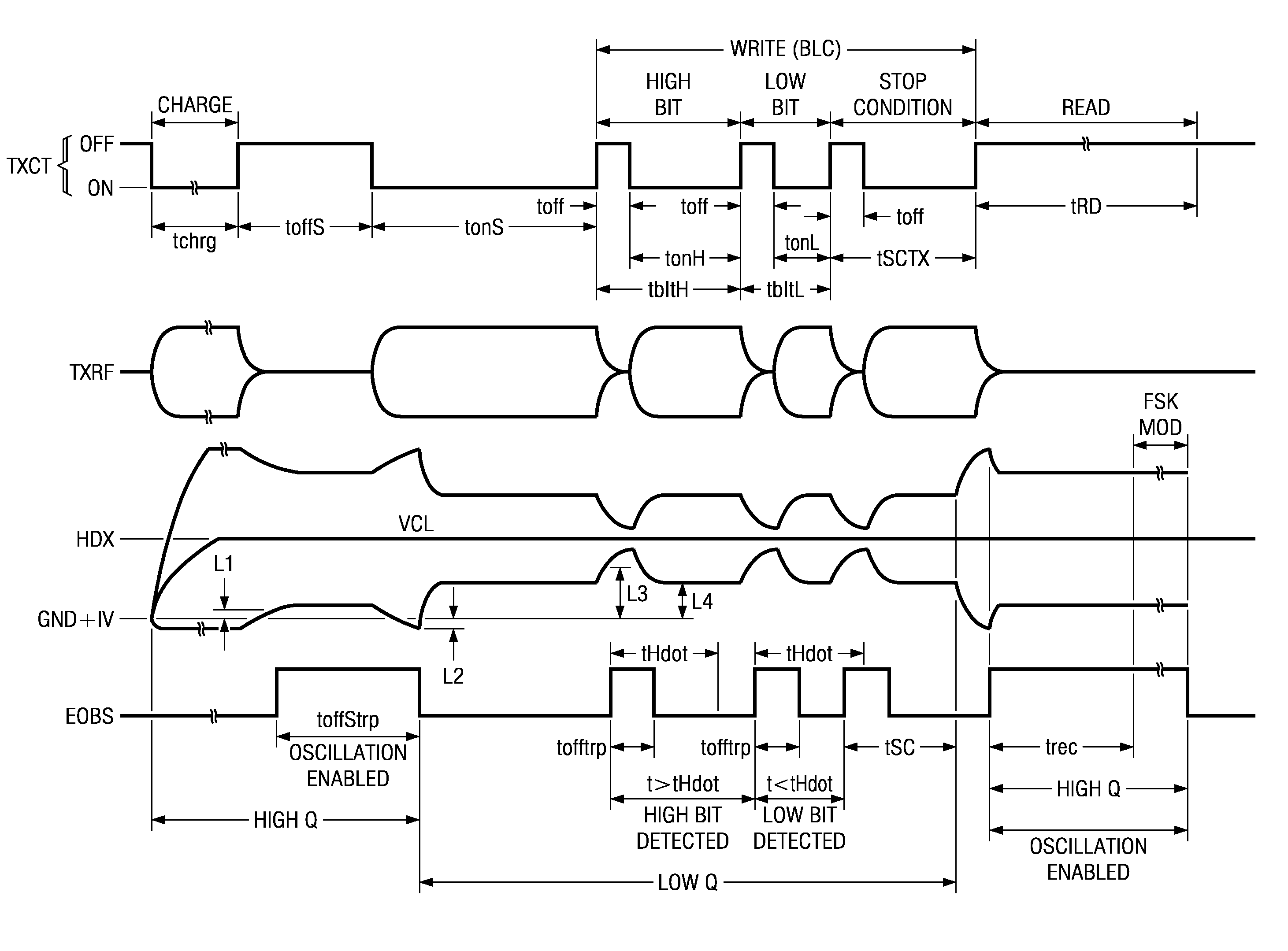
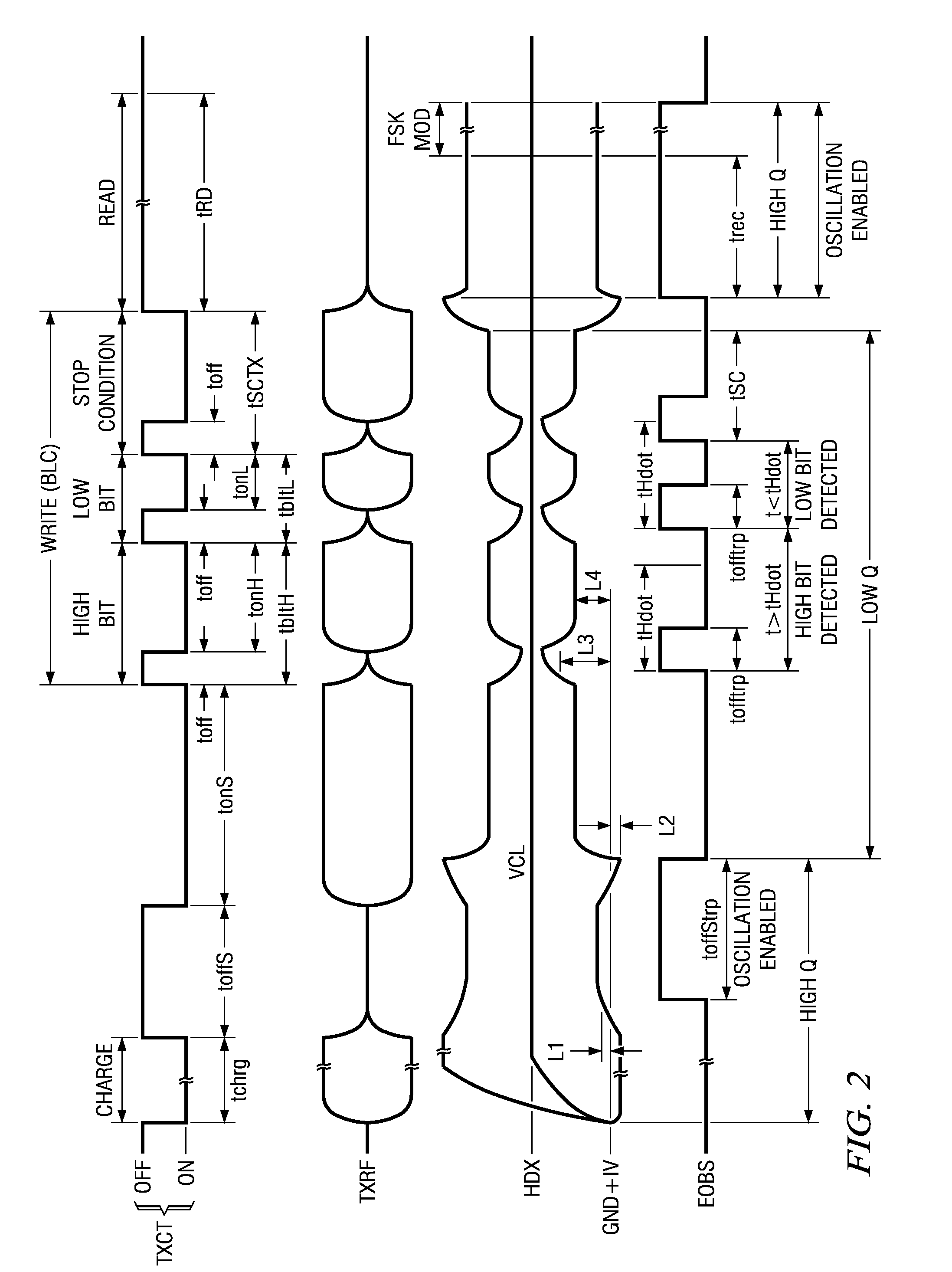
signal is absent. The present invention provides that the oscillation maintenance circuit is switched off (i.e. it is not used) during Low Q mode so that the OFF periods, where the external
RF excitation is absent, become short and stable and the overall
power consumption in the RFID transponder is reduced. Further, since the OFF periods can be very short, none or only a few
clock cycles can get lost, even without an internal reference
clock. Therefore, the present invention provides further that the information, i.e. the difference between a high bit and low bit, is coded in the different lengths of the respective ON periods. Since the OFF periods have the same lengths and the lengths of the ON periods vary, the ratio ON to OFF can be chosen such that a loss of only a few clock cycles during an OFF period is not relevant for the determination of the received
data bits (i.e. for the decision whether the bit was high or low).
[0012]A RFID
system according to an aspect of the present invention comprises a R / W-unit and a RFID transponder. The RFID transponder is implemented according to the aspects as set out before. Accordingly, the RFID transponder has a high quality factor antenna, and a
resonance capacitor coupled with the high quality factor antenna for providing a resonant circuit. The RFID transponder is adapted to vary the quality factor of the resonant circuit such that the quality factor is low during downlink data transmission when the RFID transponder receives data through the antenna, and the quality factor is high during uplink data transmission, when the RFID transponder transmits data. The R / W-unit is adapted to transmit data during downlink data transmission with an increased
data rate. In particular, the R / W-unit is adapted to profit from the reduced OFF periods, which can be used in a downlink burst modulation, when the RFID transponder has a low quality factor of the resonant circuit.
[0013]The present invention relates also to a R / W-unit, which is adapted to communicate with a RFID transponder, which can adjust the quality factor of the resonant circuit in accordance with the above aspects of the invention. Therefore, the present invention also provides a data protocol for downlink data communication that profits from the increased
data rate, which can be used for a RFID transponder that can switch the quality factor of the resonant circuit to a lower value during downlink data transmission.

