
Semiconductor package with incorporated inductance element

a technology of inductance element and semiconductor, applied in the direction of semiconductor/solid-state device details, semiconductor devices, electrical apparatus, etc., can solve the problems of affecting the performance of the processor, affecting the response time, and damaging the processor

Inactive Publication Date: 2016-05-12
QUALCOMM INC
View PDF0 Cites 21 Cited by
  • Summary
  • Abstract
  • Description
  • Claims
  • Application Information

AI Technical Summary

Benefits of technology

The text describes the difficulty of adding a voltage regulator to a semiconductor package that contains a processor. This is because voltage regulators contain large passive components like inductors and capacitors that increase the size and cost of the package. Attempts to reduce the size of these components result in poor quality factors. The technical effect of this patent is to solve this problem by providing a way to add a voltage regulator without increasing the size or cost of the semiconductor package.

Problems solved by technology

Voltages outside of the acceptable range can damage the processor or cause erratic results.
However, a voltage drop is known to occur due to the distance between the voltage regulator and the processor, which has a negative impact on the performance of the processor.
Moreover, the distance between the voltage regulator and the processor can result in slow response times. In the event that current transients are too fast for the voltage regulator to respond, decoupling capacitors are sometimes provided additional power to the processor.
However, the decoupling capacitors can occupy a large area, which has a negative impact on overall size.
Inductors and capacitors are large, which increases the overall size of the semiconductor package, and / or the manufacturing cost of the semiconductor package.
Attempts to reduce the size of passive components typically results in passive components with a low quality factor.
A quality factor for passive components embedded in a die can be low because the passive components are manufactured thin to fit in the die.
As the amount of conducting material shrinks, conductive or magnetic losses increase and degrade the quality factor.

Method used


Image

  • Semiconductor package with incorporated inductance element
  • Semiconductor package with incorporated inductance element
  • Semiconductor package with incorporated inductance element

Examples


Embodiment Construction

[0026]Aspects of the disclosure are disclosed in the following description and related drawings directed to specific aspects of the disclosure. Alternate aspects may be devised without departing from the scope of the invention. Additionally, well-known elements of the invention will not be described in detail or will be omitted so as not to obscure the relevant details of the invention.

[0027]The words “exemplary” and / or “example” are used herein to mean “serving as an example, instance, or illustration.” Any aspect described herein as “exemplary” and / or “example” is not necessarily to be construed as preferred or advantageous over other aspects. Likewise, the term “aspects of the invention” does not require that all aspects of the invention include the discussed feature, advantage or mode of operation.

[0028]As used herein, the term “vertical” is generally defined with respect to a surface of a substrate or carrier upon which a semiconductor package is formed. The substrate or carrie...


PUM


Abstract

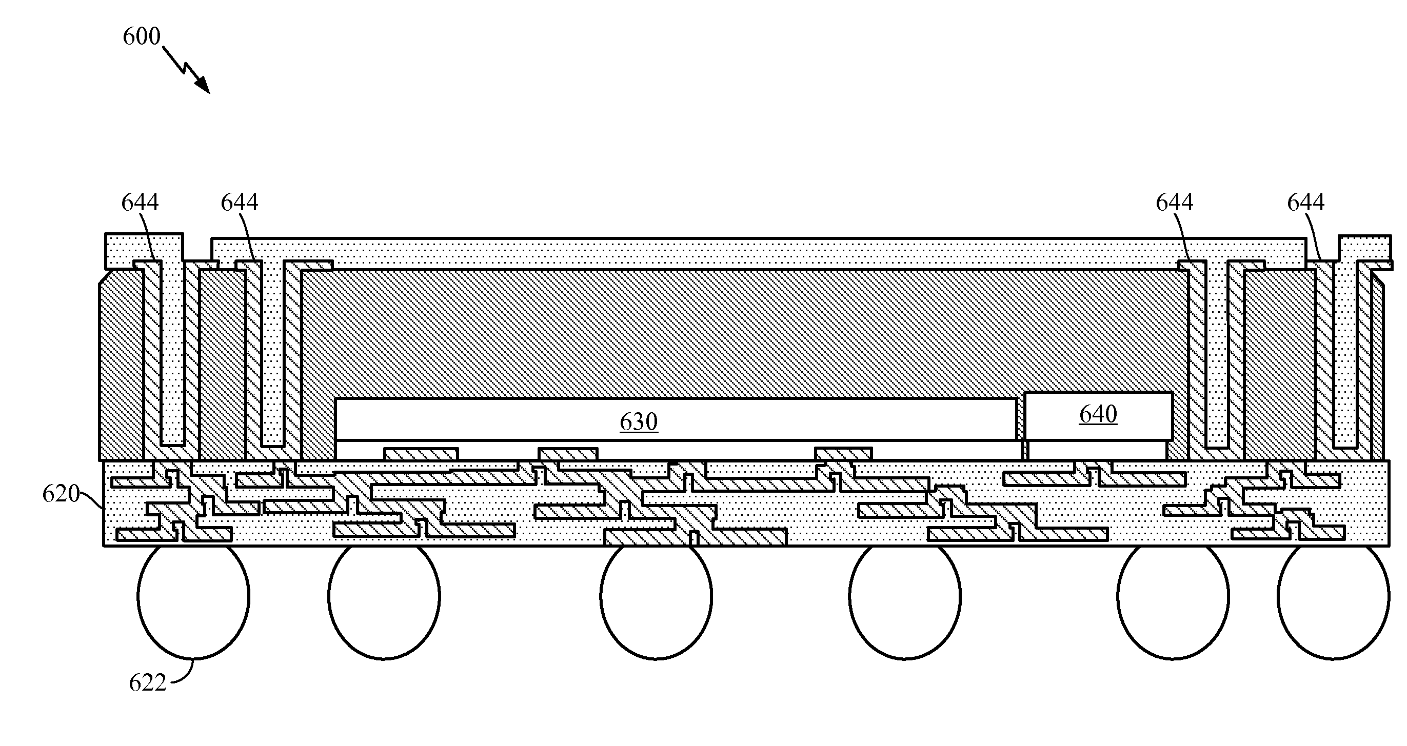
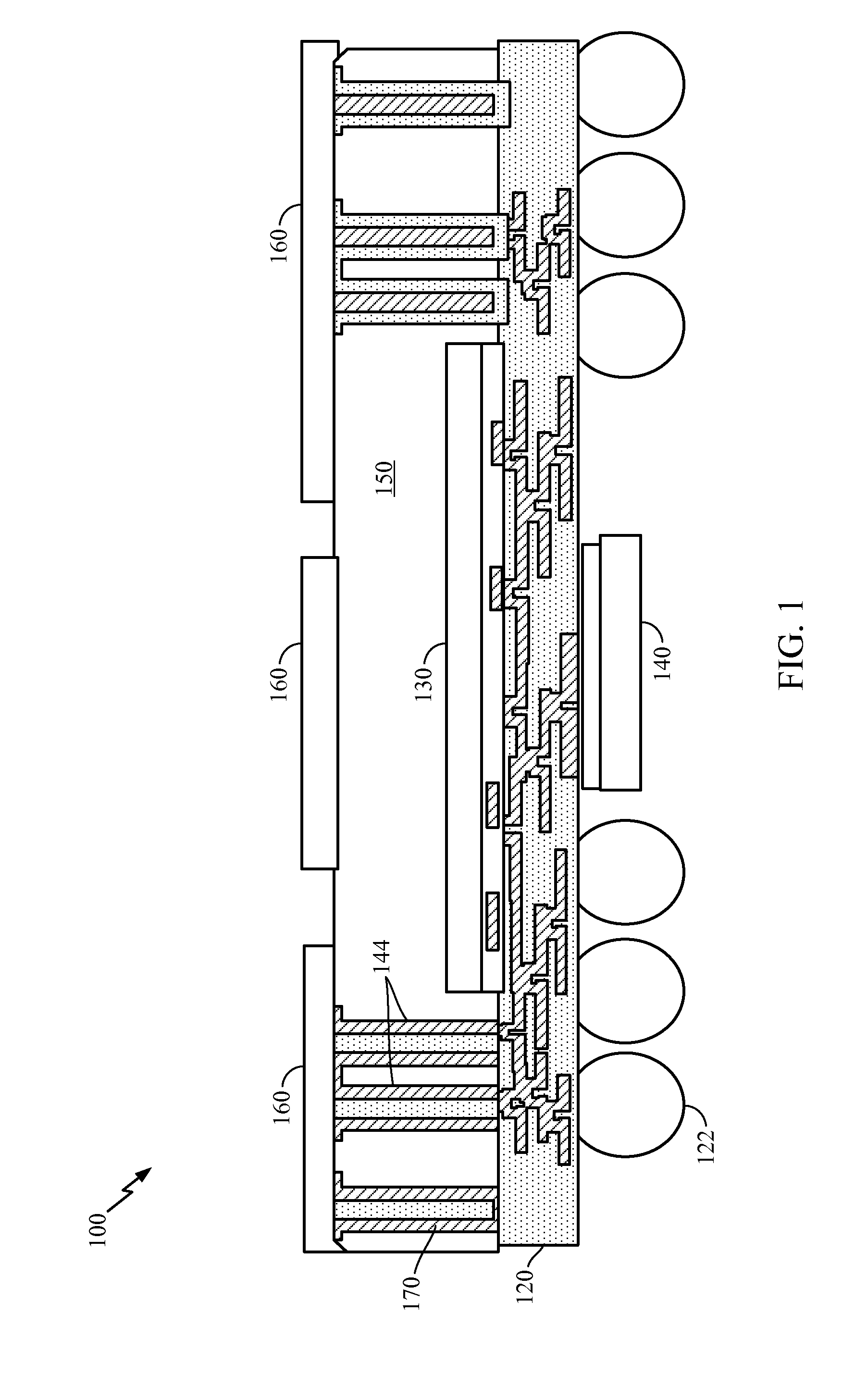
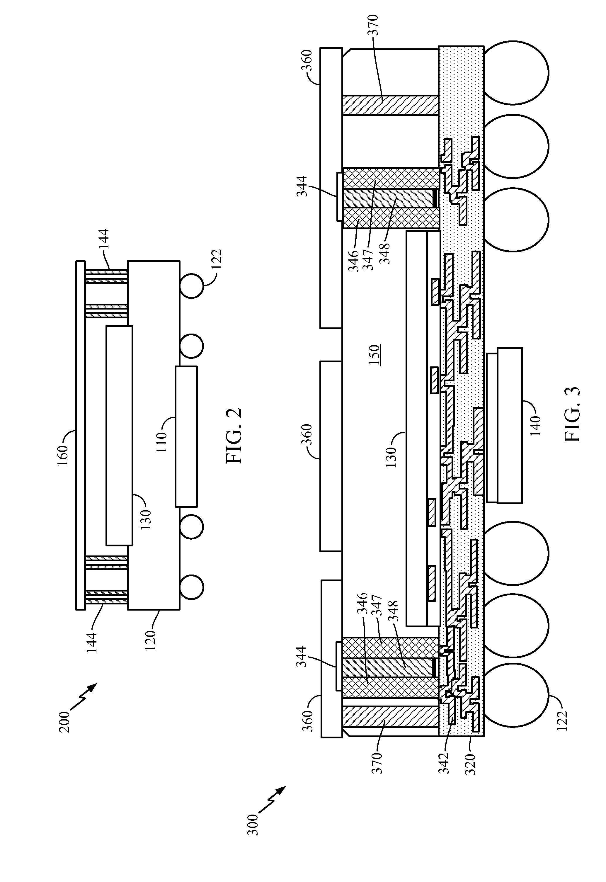
The present disclosure provides semiconductor packages and methods for fabricating semiconductor packages. The semiconductor package may comprise a semiconductor device mounted to a first substrate, a voltage regulator mounted to the first substrate and coupled to the semiconductor device, and an inductive element located on a perimeter of the semiconductor device and coupled to the voltage regulator, wherein the inductive element is formed by a plurality of interconnected conductive elements extending vertically from the first substrate.

Description

INTRODUCTION[0001]Aspects of this disclosure relate generally to semiconductor packages, and more particularly to improving power transmission to integrated circuits within semiconductor packages.[0002]A conventional semiconductor package includes a semiconductor device, for example, a processor integrated circuit (IC), memory IC, die, chip, or the like. The processor is coupled to a voltage regulator, for example, a voltage regulator IC. The voltage regulator ensures a constant voltage supply is provided to the processor. This is an important function, because the transistors in the processor have narrow voltage tolerances. Voltages outside of the acceptable range can damage the processor or cause erratic results.[0003]The processor is mounted on a package substrate, and the package substrate is mounted on a printed circuit board (PCB). Conventionally, a semiconductor device is mounted on one portion of the PCB, and a voltage regulator is mounted on another. The voltage supplied by...

Claims


Application Information

Patent Timeline
IPC IPC(8): H01L25/16H01L23/522H01L23/498H01L21/683H01L21/56H01L21/768H01L21/48H01L25/065H01L25/00
CPCH01L25/16H01L25/0657H01L23/5227H01L23/49816H01L25/50H01L2221/68359H01L21/768H01L21/486H01L21/6835H01L2225/06548H01L21/565H01L21/568H01L23/295H01L23/3128H01L23/49822H01L23/49827H01L23/5389H01L24/19H01L24/20H01L25/0655H01L25/105H01L2224/04105H01L2224/12105H01L2224/16227H01L2224/24195H01L2224/32225H01L2224/81005H01L2225/06517H01L2225/06572H01L2225/1023H01L2225/1035H01L2225/1041H01L2225/1058H01L2924/14H01L2924/1432H01L2924/1434H01L2924/15192H01L2924/15311H01L2924/15331H01L2924/181H01L2924/19042H01L2924/19105H01L2924/00012
Inventor GU, SHIQUNRADOJCIC, RATIBORBADAROGLU, MUSTAFASHI, CHUNLEIPAN, YUANCHENG CHRISTOPHER
Owner QUALCOMM INC
Learn More