Thin-film bandpass filter using inductor-capacitor resonators

Active Publication Date: 2007-06-07
TDK CORPARATION
View PDF8 Cites 18 Cited by
  • Summary
  • Abstract
  • Description
  • Claims
  • Application Information

AI Technical Summary

Benefits of technology

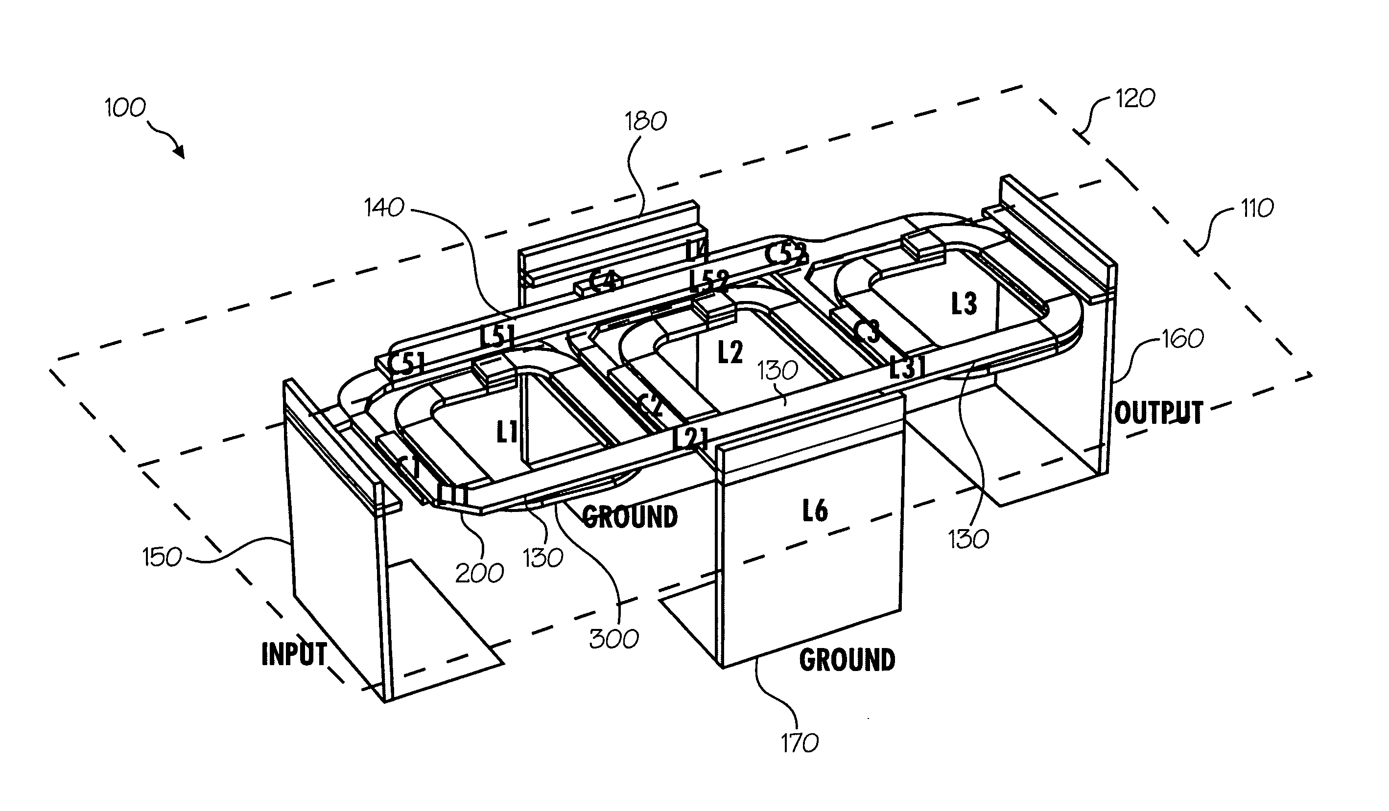
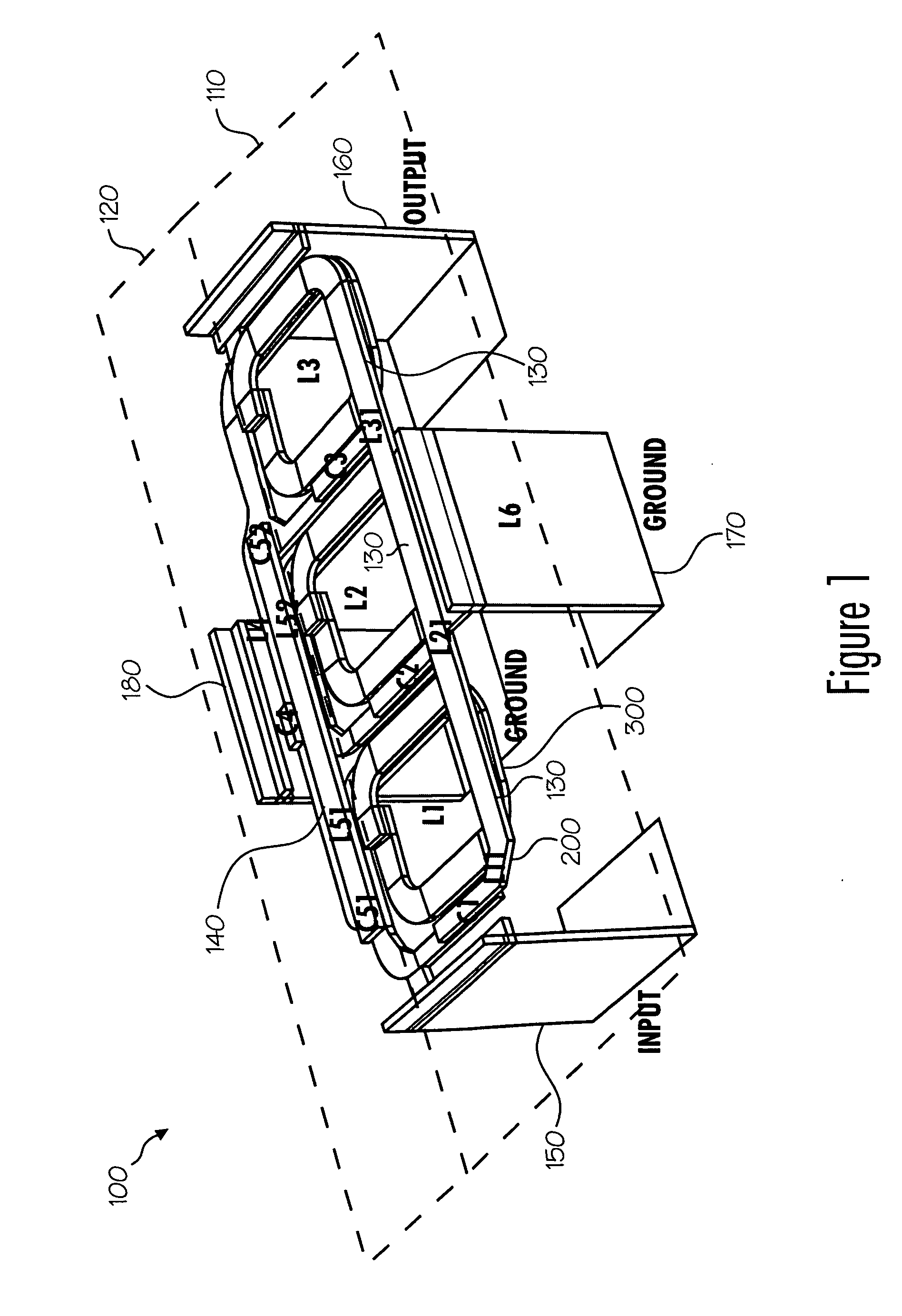
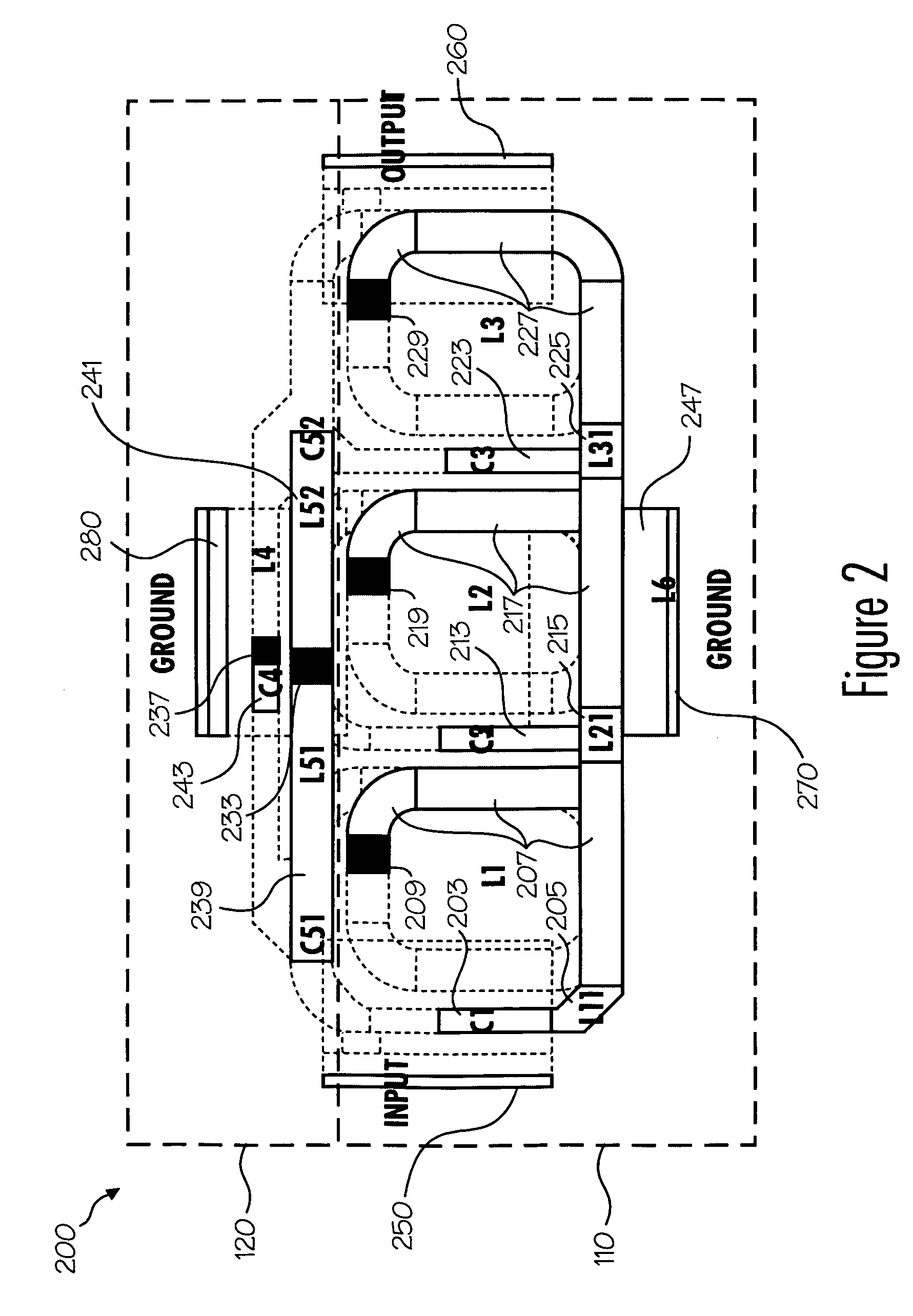
[0009] In view of the foregoing, the invention provides a band pass filter in which inductor-capacitor (LC) resonators are constructed in one region of the filter and a coupling ne

Problems solved by technology

Such, overlap generally deteriorates the qu

Method used


Image

  • Thin-film bandpass filter using inductor-capacitor resonators
  • Thin-film bandpass filter using inductor-capacitor resonators
  • Thin-film bandpass filter using inductor-capacitor resonators

Examples


Embodiment Construction

[0002] 1. Field of the Invention

[0003] The present invention relates to a bandpass filter, and more specifically to a thin-film bandpass filter.

[0004] 2. Background of the Invention

[0005] In recent years, marked advances in the miniaturization of mobile communication terminals, such as mobile phones and Wireless LAN (Local Area Network) routers, has been achieved due to the miniaturization of the various components incorporated therein. One of the most important components incorporated in a communication terminal is the filter.

[0006] In particular, bandpass filters are often used in communication applications for blocking or filtering signals with frequencies outside a certain passband. For example, Bluetooth and Wireless Local Area Network (WLAN) use the 2.4 GHz band for data communication. Nearby frequency bands used for other communication systems include GSM-900 (880-960 MHz), GSM-1800 (1710-1990 MHz, also called PCS in Hong Kong and United Kingdom) and WCDMA (2110-2170 MHz)...


PUM


Abstract

A bandpass filter including one or more metal layers, each layer having a first region and a second region. The filter also includes two or more LC resonators and one or more coupling networks for connecting the two or more LC resonators in parallel. The two or more LC resonators are contained within the first region of the one or more layers and the one or more coupling networks are contained in the second region of the one or more layers.

Description

CROSS-RELATED APPLICATIONS [0001] This application claims the benefit of Provisional Patent Application No. 60 / 748,045 by Richard Chen filed on Dec. 6, 2005 and titled “Bandpass Filter” which is hereby incorporated by reference herein.DESCRIPTION OF THE INVENTION [0002] 1. Field of the Invention [0003] The present invention relates to a bandpass filter, and more specifically to a thin-film bandpass filter. [0004] 2. Background of the Invention [0005] In recent years, marked advances in the miniaturization of mobile communication terminals, such as mobile phones and Wireless LAN (Local Area Network) routers, has been achieved due to the miniaturization of the various components incorporated therein. One of the most important components incorporated in a communication terminal is the filter. [0006] In particular, bandpass filters are often used in communication applications for blocking or filtering signals with frequencies outside a certain passband. For example, Bluetooth and Wirele...

Claims


Application Information

Patent Timeline
IPC IPC(8): H03H7/01
CPCH01F17/0006H01F27/40H01L23/66H03H1/00H01L24/11H03H7/175H03H7/1708H03H7/1791H03H7/0115H01L2924/12042H01L2924/00H03H9/205H03H7/01
Inventor CHEN, QIANG RICHARD
Owner TDK CORPARATION
Why Eureka
Try Eureka