Side blowing type fan

A side-blown fan and air inlet technology, which is applied to non-variable-capacity pumps, non-displacement pumps, components of pumping devices for elastic fluids, etc. The effect of reducing operating noise

Active Publication Date: 2009-05-20
DELTA ELECTRONICS INC
View PDF0 Cites 2 Cited by
  • Summary
  • Abstract
  • Description
  • Claims
  • Application Information

AI Technical Summary

Problems solved by technology

However, although this situation increases the air intake, it also relatively reduces the operating air pressure substantially, so that the air output does not increase substantially, and may even decrease.

Method used


Image

  • Side blowing type fan
  • Side blowing type fan

Examples


Embodiment Construction

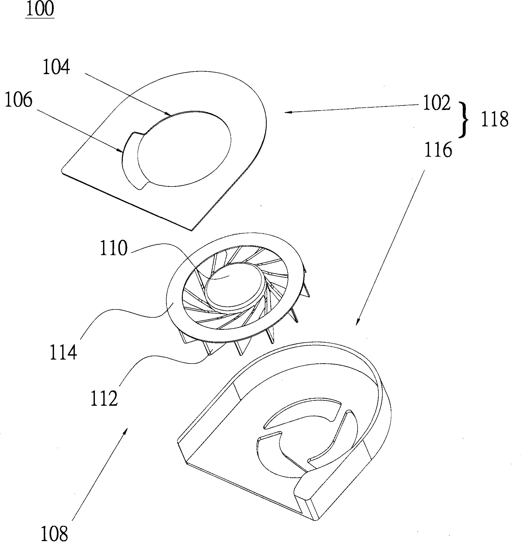
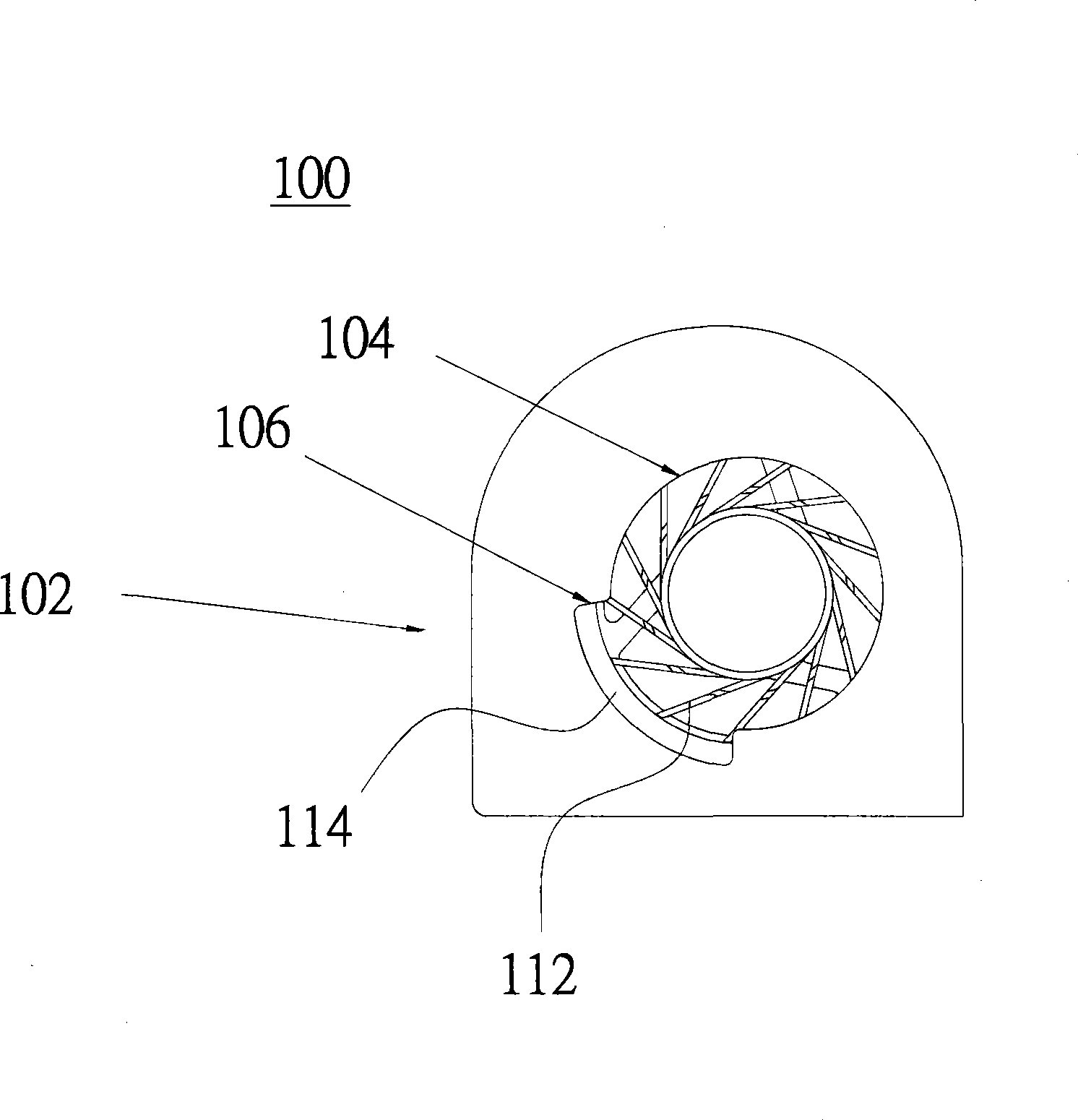
[0023] Please refer to figure 1 and figure 2 , The side blowing fan 100 of the present invention includes a first housing 102 , a second housing 116 and an impeller 108 . The side blowing fan may be a blower fan.

[0024] The first housing 102 has a main air inlet 104 and at least one auxiliary air inlet 106 . The first housing 102 and the second housing 116 are correspondingly connected to form a housing 118 to form an accommodating space. The shape of the main air inlet 104 can be circular, oval, polygonal or irregular. Preferably, the main air inlet 104 is coaxial with the impeller 108 .

[0025] The auxiliary air inlet 106 can extend outward from the edge of the main air inlet 104 , or can be independent of the main air inlet 104 . The shape of the auxiliary air inlet 106 can be circular, fan-shaped, polygonal, circular hole, elliptical hole or sausage-shaped hole. The number of auxiliary air inlets 106 can be one, or two or more.

[0026] The impeller 108 is dispo...


PUM


Abstract

The invention discloses a side-blow fan, which comprises a shell and an impeller, wherein the shell is provided with a master air inlet and at least one auxiliary air inlet. The impeller is arranged in the shell and comprises a hub part, a plurality of blades and at least one ring plate. The blades are arranged around the hub part. The ring plate is connected with the blades, and shields partial auxiliary air inlet. Because of the additional auxiliary air inlet, the side-blow fan can increase air input. In addition, the side-blow fan is also provided with the ring plate, and uses the ring plate to shield partial auxiliary air inlet so as to change the flow field at the auxiliary air inlet, thereby achieving an effect of great reducing operation noises.

Description

technical field [0001] The invention relates to a side-blowing fan, in particular to a side-blowing fan which can increase air volume and reduce running noise. Background technique [0002] In systems that require high back pressure, blowers are currently used to provide higher wind pressure to the system, thereby enabling the system to obtain higher back pressure. Moreover, in the existing blower structure, only a single air inlet is formed on one side of the blower casing, and the size of the air inlet is smaller than the size of the inner impeller of the blower to a certain extent. At this time, when the blower is running, although it can provide a large wind pressure, it is accompanied by a substantial increase in noise and a large reduction in the air intake. [0003] In order to increase the air intake volume, another existing air blower designs the size of the aforementioned air inlet to be similar to the size of the inner impeller of the blower. However, although t...

Claims


Application Information

Patent Timeline
Patent Type & Authority Applications(China)
IPC IPC(8): F04D17/08F04D29/42F04D29/30
Inventor 陈仕瀚
Owner DELTA ELECTRONICS INC
Why Eureka
Try Eureka