Telescopic cross magnet yoke fluorescent magnetic powder flaw detection machine

A fluorescent magnetic powder, telescopic technology, applied in the direction of material magnetic variables, etc., can solve the problem that the magnetic pole of the crossed yoke cannot be automatically compensated, and achieve stable flaw detection sensitivity, stable effect, and ensure the effect of magnetic field strength.

Inactive Publication Date: 2009-05-20
瑞迪世纪(北京)探伤设备有限公司
View PDF3 Cites 20 Cited by
  • Summary
  • Abstract
  • Description
  • Claims
  • Application Information

AI Technical Summary

Problems solved by technology

[0005] In view of this, in order to overcome the shortcoming that the magnetic poles of the cross yoke in the prior art cannot automatically compensate the contact gap with the workpiece to ensure the strength of the magnetic field, the present invention provides a magnetic pole telescopic cross yoke magnetic particle flaw detector

Method used


Image

  • Telescopic cross magnet yoke fluorescent magnetic powder flaw detection machine
  • Telescopic cross magnet yoke fluorescent magnetic powder flaw detection machine
  • Telescopic cross magnet yoke fluorescent magnetic powder flaw detection machine

Examples


Embodiment 1

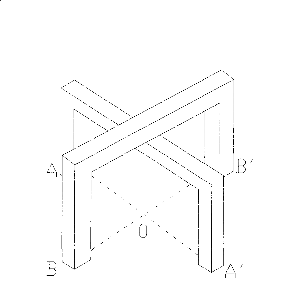
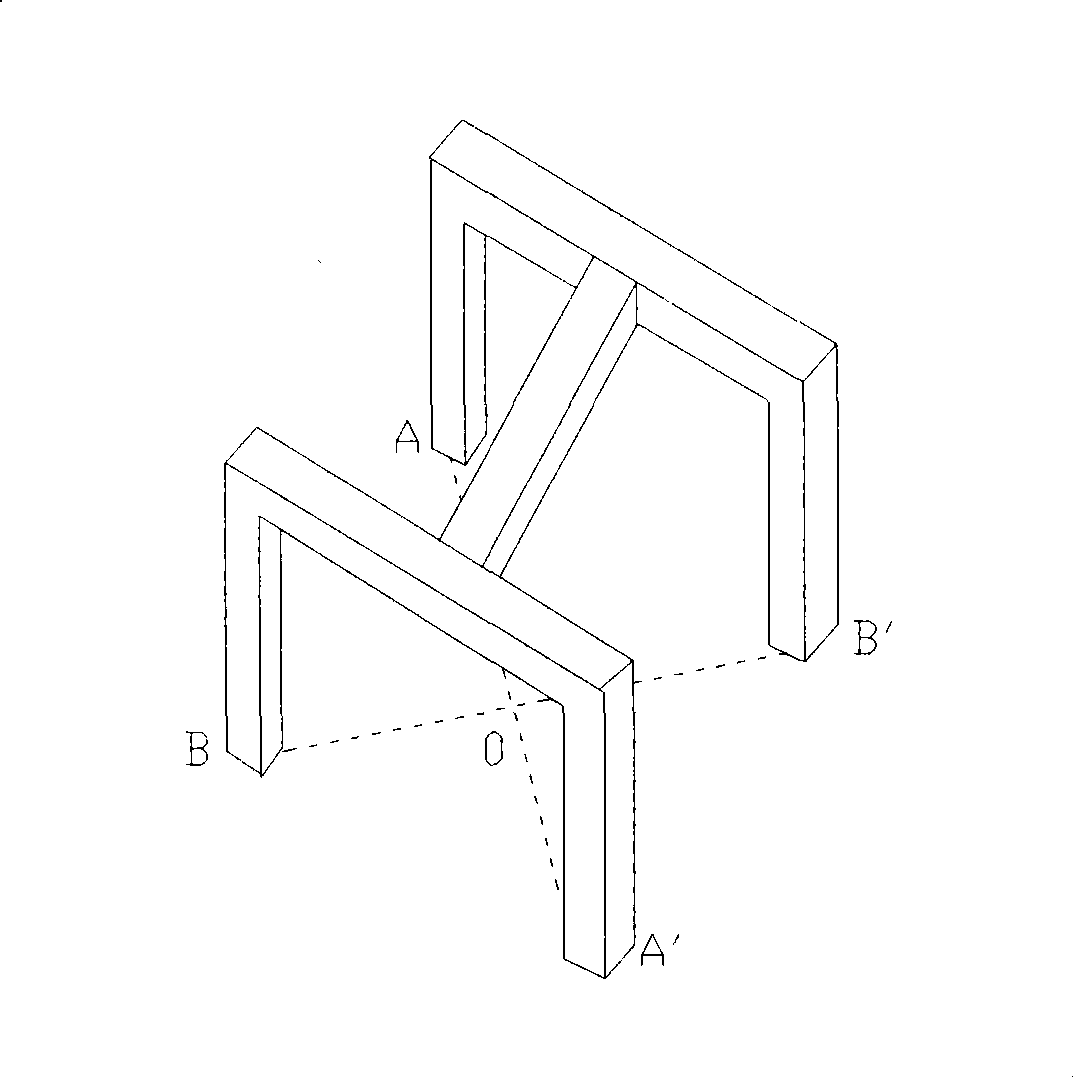
[0046] A telescopic cross yoke fluorescent magnetic particle flaw detector, which is composed of a magnetic suspension liquid spray recovery device 1 and a cross yoke 2, the cross yoke is composed of a fixed yoke 3 and a movable yoke 4, and the cross yoke is connected with the workpiece to be tested The part parallel to the surface forms a fixed yoke, and the part perpendicular to the surface of the workpiece to be measured in the cross yoke forms a movable yoke. The four corners of the fixed yoke are fixedly connected to a sliding sleeve 5, and the sliding sleeve is perpendicular to the plane formed by the fixed yoke. , the movable yoke passes through the sliding sleeve and is slidably connected with the sleeve. The movable yoke is divided into compression spring 6, sliding area 7, magnetizing coil 8 and magnetic pole 9 from top to bottom. The sliding area of ​​the movable yoke can be Sliding up and down in the sliding sleeve, the upper part of the compression spring is provid...

Embodiment 2

[0048] It is basically the same as Embodiment 1, except that a magnetic suspension spraying recovery device 1 is installed at the front end of the crossed yoke in the traveling direction, and an ultraviolet lamp 20 and an image acquisition charge-coupled device 13 are arranged at the rear end of the crossed yoke in the traveling direction. Image Acquisition The distance between the charge-coupled device and the cross yoke is 300mm.

Embodiment 3

[0050] It is basically the same as Embodiment 2, except that the magnetic particle flaw detection machine is also provided with a lead screw that is parallel to the surface 14 of the workpiece to be tested and moves at a uniform speed, and the magnetic suspension spray recovery device 1, the cross yoke 2 and the image acquisition charge coupling The device is loaded on a lead screw. The speed of uniform motion is 1 m / min.


PUM


Abstract

The invention provides a telescopic crossed yoke fluorescent magnetic powder inspection machine. A crossed yoke comprises a fixed yoke parallel to the surface of a workpiece to be tested and a moving yoke perpendicular to the surface of the workpiece to be tested, the moving yoke passes through a sliding bushing and is in sliding connection with the fixed yoke, and the moving yoke is provided with a pressure spring. The invention successfully realizes that each magnetic pole of the magnetic powder inspection machine has telescopic function so as to closely contact the workpiece by dividing the crossed yoke into the fixed yoke and the moving yoke, thereby guaranteeing the magnetic-field intensity during the fault detection. The magnetic powder inspection machine is also provided with a CCD image acquisition device, and realizes the program control of working procedures of feeding, magnetization, CCD observation and discharge as well as on-line detection monitoring and automatic fault detection through the program control operation of a PLC.

Description

technical field [0001] The invention relates to a magnetic particle flaw detector, in particular to a cross yoke fluorescent magnetic particle flaw detector. Background technique [0002] At present, the magnetic particle inspection method has been widely used in various fields of industry at home and abroad. The basic principle of magnetic particle inspection is: when ferromagnetic materials are magnetized in a magnetic field, defects or changes in the structure of the surface and near the surface of the material will cause local damage. The magnetic permeability changes, that is, the magnetic resistance increases, so that the magnetic flux in the magnetic circuit is correspondingly distorted: a part of the magnetic flux directly passes through the defect, a part of the magnetic flux bypasses the defect inside the material, and a part of the magnetic flux leaves the surface of the material. The leakage field is formed on the surface of the material by air bypassing the defe...

Claims


Application Information

Patent Timeline
Patent Type & Authority Applications(China)
IPC IPC(8): G01N27/84
Inventor 于成金陈健生兰长生宋士兵胡星波朱理
Owner 瑞迪世纪(北京)探伤设备有限公司
Why Eureka
Try Eureka